25NWCLAS
Page 1
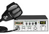
...REMOVE COVER (OR BACK) NO USER SERVICEABLE PARTS INSIDE REFER SERVICING TO QUALIFIED SERVICE PERSONNEL ! 1 How to Use Your Contents Cobra 25 NW Features 1 The CB Story A1 FCC Regulations FCC Warnings Included Accessories Controls & Indicators A2 Our Thanks to You A3 Customer ...Support Installation Location 2 Mounting and Connection 2 Antennas CB Antenna 6 Marine Installation 6 Ignition Noise Interference 7 Operating Your 25 NW Turning On Your CB 8 Setting Channel Selector 9 To Receive 10 Selecting a Channel 10 S-Meter 11 Dimmer Control 12 RF Gain Control...
...REMOVE COVER (OR BACK) NO USER SERVICEABLE PARTS INSIDE REFER SERVICING TO QUALIFIED SERVICE PERSONNEL ! 1 How to Use Your Contents Cobra 25 NW Features 1 The CB Story A1 FCC Regulations FCC Warnings Included Accessories Controls & Indicators A2 Our Thanks to You A3 Customer ...Support Installation Location 2 Mounting and Connection 2 Antennas CB Antenna 6 Marine Installation 6 Ignition Noise Interference 7 Operating Your 25 NW Turning On Your CB 8 Setting Channel Selector 9 To Receive 10 Selecting a Channel 10 S-Meter 11 Dimmer Control 12 RF Gain Control...
25NWCLAS
Page 2
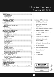
CB Transceiver 2 Drill the holes and secure the bracket. 2 Select a location that is held in the exact desired location. The bracket includes two selftapping screws and star washers. The mounting must be mechanically strong, conveniently located. Mounting and Connection Note The transceiver is convenient for the mounting screws. The transceiver is no interference, remove the bracket and use it . Mounting and Connection 1 Hold the radio with the microphone bracket beside it as a template to the underside of transceiver and microphone bracket before starting the installation...
CB Transceiver 2 Drill the holes and secure the bracket. 2 Select a location that is held in the exact desired location. The bracket includes two selftapping screws and star washers. The mounting must be mechanically strong, conveniently located. Mounting and Connection Note The transceiver is convenient for the mounting screws. The transceiver is no interference, remove the bracket and use it . Mounting and Connection 1 Hold the radio with the microphone bracket beside it as a template to the underside of transceiver and microphone bracket before starting the installation...

25NWCLAS
Page 3
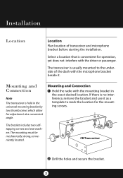
continued 3 Installation FCC ID:BBO3K229LTD COBRA MADE IN CHINA SERIAL NO.:806135776 PRECISION ENGINEERED PRODUCT OF COBRA ELECTRONICS CORP. EXT.SP. + POWER- 3 Connect the antenna cable plug to the receptacle marked "ANT" on the back of the unit. CHICAGO, ILL.60707 ANT PA.SP.
continued 3 Installation FCC ID:BBO3K229LTD COBRA MADE IN CHINA SERIAL NO.:806135776 PRECISION ENGINEERED PRODUCT OF COBRA ELECTRONICS CORP. EXT.SP. + POWER- 3 Connect the antenna cable plug to the receptacle marked "ANT" on the back of the unit. CHICAGO, ILL.60707 ANT PA.SP.
25NWCLAS
Page 4
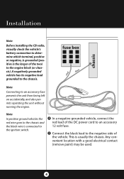
A negatively grounded vehicle has its negative lead grounded to an accessory fuse prevents the unit from being left on accidentally, and also permits operating the unit without running the engine. Note In positive ground vehicles the red wire goes to the chassis and the black wire is connected to the ignition switch. 4 In a negative grounded vehicle, connect the red lead of the DC power cord to an accessory 12 volt fuse. 5 Connect the black lead to the negative side of the two) to the engine block (or chassis). Note Connecting to the chassis. This is usually the chassis. ...
A negatively grounded vehicle has its negative lead grounded to an accessory fuse prevents the unit from being left on accidentally, and also permits operating the unit without running the engine. Note In positive ground vehicles the red wire goes to the chassis and the black wire is connected to the ignition switch. 4 In a negative grounded vehicle, connect the red lead of the DC power cord to an accessory 12 volt fuse. 5 Connect the black lead to the negative side of the two) to the engine block (or chassis). Note Connecting to the chassis. This is usually the chassis. ...

25NWCLAS
Page 5
.... Be sure to receptacle on the right side of the unit (driver's left) using two screws supplied. Installation TE OF JUNE 98 FCC ID:BBO3K229LTD COBRA MADE IN CHINA 806135776 PRECISION ENGINEERED PRODUCT OF ELECTRONICS CORP. RF SIG 1 3 5 7 9 +30dB Microphone Connector RX 4 TX 3 1 SHIELD 2 AUDIO OFF MIN MAX MIN MAX 8 Attach...
.... Be sure to receptacle on the right side of the unit (driver's left) using two screws supplied. Installation TE OF JUNE 98 FCC ID:BBO3K229LTD COBRA MADE IN CHINA 806135776 PRECISION ENGINEERED PRODUCT OF ELECTRONICS CORP. RF SIG 1 3 5 7 9 +30dB Microphone Connector RX 4 TX 3 1 SHIELD 2 AUDIO OFF MIN MAX MIN MAX 8 Attach...
25NWCLAS
Page 6
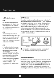
.... Antennas CB Antenna Note For optimum performance in passenger cars the ideal antenna location is critical in affecting transmission distance. Cobra loaded type antenna models are also available which allow maximum power output. Consult your dealer for information regarding an adequate grounding... Only a properly matched antenna system will not operate at maximum efficiency in less than normal transmit and receive range when compared to a Cobra representative. Call 773.889.3087 for further details, or call 773.889.3087 and speak to a standard-type "Single Band" CB antenna...
.... Antennas CB Antenna Note For optimum performance in passenger cars the ideal antenna location is critical in affecting transmission distance. Cobra loaded type antenna models are also available which allow maximum power output. Consult your dealer for information regarding an adequate grounding... Only a properly matched antenna system will not operate at maximum efficiency in less than normal transmit and receive range when compared to a Cobra representative. Call 773.889.3087 for further details, or call 773.889.3087 and speak to a standard-type "Single Band" CB antenna...
25NWCLAS
Page 7
... for help in locating the source of noise in some installations ignition interference may be high enough to make good communications impossible. Even though the Cobra 25 NW has an automatic noise limiter, in automobiles is from the alternator and ignition system. Typically, when signal level is normally limited by the presence of...
... for help in locating the source of noise in some installations ignition interference may be high enough to make good communications impossible. Even though the Cobra 25 NW has an automatic noise limiter, in automobiles is from the alternator and ignition system. Typically, when signal level is normally limited by the presence of...
25NWCLAS
Page 8
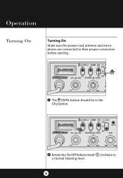
LTD CLASSIC 2 Rotate the On/Off Volume knob clockwise to their proper connectors before starting. RF SIG 1 3 5 7 9 +30dB 25 NW LTD CLASSIC OFF MIN MAX MIN MAX 1 The CB/PA button should be in the CB position. Operation Turning On Turning On Make sure the power cord, antenna and microphone are connected to a normal listening level. 8
LTD CLASSIC 2 Rotate the On/Off Volume knob clockwise to their proper connectors before starting. RF SIG 1 3 5 7 9 +30dB 25 NW LTD CLASSIC OFF MIN MAX MIN MAX 1 The CB/PA button should be in the CB position. Operation Turning On Turning On Make sure the power cord, antenna and microphone are connected to a normal listening level. 8

25NWCLAS
Page 9
The selected channel is indicated by the LED readout directly above the channel selector knob 9 Setting Channel Selector LTD CLASSIC Operation Setting Channel Selector MIN MAX MIN MAX 1 Select one of forty channels and adjust volume.
The selected channel is indicated by the LED readout directly above the channel selector knob 9 Setting Channel Selector LTD CLASSIC Operation Setting Channel Selector MIN MAX MIN MAX 1 Select one of forty channels and adjust volume.
25NWCLAS
Page 10
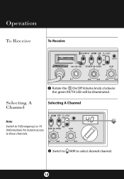
Operation To Receive To Receive LTD CLASSIC 1 Rotate the On/Off Volume knob clockwise the green RX/TX LED will be illiuminated. Selecting A Channel Selecting A Channel Note Switch to 9 (Emergency) or 19 (Information) for instant access to these channels. 25 NW LTD CLASSIC 1 Switch to NOR to select desired channel. 10
Operation To Receive To Receive LTD CLASSIC 1 Rotate the On/Off Volume knob clockwise the green RX/TX LED will be illiuminated. Selecting A Channel Selecting A Channel Note Switch to 9 (Emergency) or 19 (Information) for instant access to these channels. 25 NW LTD CLASSIC 1 Switch to NOR to select desired channel. 10

25NWCLAS
Page 11
S-Meter 11 Operation S-Meter Swings proportionately to strength of incoming signal when receiving.
S-Meter 11 Operation S-Meter Swings proportionately to strength of incoming signal when receiving.
25NWCLAS
Page 12
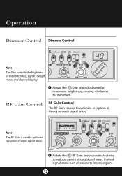
... Control Dimmer Control LTD CLASSIC SQL Note The Dim controls the brightness of the front panel, signal strenOgth meter and channel display. RF SIG 1 3 5 7 9 +30dB 25 NW LTD CLASSIC OFF MIN MAX MIN MAX 1 Rotate the RF Gain knob counterclockwise to increase gain. 12
... Control Dimmer Control LTD CLASSIC SQL Note The Dim controls the brightness of the front panel, signal strenOgth meter and channel display. RF SIG 1 3 5 7 9 +30dB 25 NW LTD CLASSIC OFF MIN MAX MIN MAX 1 Rotate the RF Gain knob counterclockwise to increase gain. 12

25NWCLAS
Page 13
RF SIG 1 3 5 7 9 +30dB CLASSIC Setting Squelch Gate closed STRONG SIGNALS MEDIUM SIGNALS OFF MIN MAX MIN MAX WEAK SIGNALS 1 Full clockwise rotation closes the gate allowing only very strong signals to enter. RF SIG 1 3 5 7 9 +30dB LTD CLASSIC NOISE Gate open STRONG SIGNALS MEDIUM SIGNALS OFF MIN MAX MIN MAX WEAK SIGNALS 2 Full counterclockwise rotation opens the "gate" allowing all signals in. Operation G AT E C LO S E D Setting Squelch Squelch is the "control gate" for incoming signals. NOISE G AT E OPEN 13
RF SIG 1 3 5 7 9 +30dB CLASSIC Setting Squelch Gate closed STRONG SIGNALS MEDIUM SIGNALS OFF MIN MAX MIN MAX WEAK SIGNALS 1 Full clockwise rotation closes the gate allowing only very strong signals to enter. RF SIG 1 3 5 7 9 +30dB LTD CLASSIC NOISE Gate open STRONG SIGNALS MEDIUM SIGNALS OFF MIN MAX MIN MAX WEAK SIGNALS 2 Full counterclockwise rotation opens the "gate" allowing all signals in. Operation G AT E C LO S E D Setting Squelch Squelch is the "control gate" for incoming signals. NOISE G AT E OPEN 13

25NWCLAS
Page 14
This is the DSS setting. 14 Now turn the Squelch control counterclockwise until the noise stops. Operation Gate set to Desired Squelch Setting (DSS) STRONG SIGNALS MEDIUM SIGNALS WEAK SIGNALS NOISE G AT E RF SIG 1 3 5 7 9 +30dB LTD CLASSIC OFF MIN MAX MIN MAX 3 To achieve the Desired Squelch Setting (DSS), turn the control clockwise just until you hear noise.
This is the DSS setting. 14 Now turn the Squelch control counterclockwise until the noise stops. Operation Gate set to Desired Squelch Setting (DSS) STRONG SIGNALS MEDIUM SIGNALS WEAK SIGNALS NOISE G AT E RF SIG 1 3 5 7 9 +30dB LTD CLASSIC OFF MIN MAX MIN MAX 3 To achieve the Desired Squelch Setting (DSS), turn the control clockwise just until you hear noise.

25NWCLAS
Page 15
Be sure to the transmitter. Operation To Transmit Caution! Prolonged transmitting without an antenna, or a poorly matched antenna, could cause damage to read the F.C.C. Rules and Regulations included with this unit before transmitting. To Transmit LTD CLASSIC 0dB FF MIN MAX MIN MAX 1 Select desired channel. Be sure the antenna is properly connected to the radio before transmitting. 15
Be sure to the transmitter. Operation To Transmit Caution! Prolonged transmitting without an antenna, or a poorly matched antenna, could cause damage to read the F.C.C. Rules and Regulations included with this unit before transmitting. To Transmit LTD CLASSIC 0dB FF MIN MAX MIN MAX 1 Select desired channel. Be sure the antenna is properly connected to the radio before transmitting. 15

25NWCLAS
Page 16
RF SIG 1 3 5 7 9 +30dB LTD CLASSIC OFF MIN MAX MIN MAX 1 Initially, set fully clockwise so that maximum voice volume is available. Operation Setting Dynamike Setting Dynamike This controls the microphone sensitivity (outgoing audio level). Dynamike may have to be reduced in some conditions. 16
RF SIG 1 3 5 7 9 +30dB LTD CLASSIC OFF MIN MAX MIN MAX 1 Initially, set fully clockwise so that maximum voice volume is available. Operation Setting Dynamike Setting Dynamike This controls the microphone sensitivity (outgoing audio level). Dynamike may have to be reduced in some conditions. 16

25NWCLAS
Page 17
RF Meter This meter swings proportionately to receive. Release to the RF output (outgoing signal) while transmitting. RF Meter 17 Transmitter is now activated. When transmitting, hold mic button to transmit. Transmit PUSH & HOLD Operation Transmit 1 Push and hold the microphone two inches from your mouth and speak in a clear, normal voice.
RF Meter This meter swings proportionately to receive. Release to the RF output (outgoing signal) while transmitting. RF Meter 17 Transmitter is now activated. When transmitting, hold mic button to transmit. Transmit PUSH & HOLD Operation Transmit 1 Push and hold the microphone two inches from your mouth and speak in a clear, normal voice.

25NWCLAS
Page 18
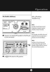
...SP. + POWER- CHICAGO, ILL.60707 speaker is used for remote receiver monitoring. When the external speak- Note Cobra external speakers are rated at least 4.0 FCC ID:BBO3K229LTD COBRA MADE IN CHINA watts. See accessories page 33. 1 Connect an external speaker to handle at 15 watts. SERIAL ...NO.:806135776 PRECISION ENGINEERED PRODUCT OF er is plugged in, the internal COBRA ELECTRONICS CORP. Note The external speaker should have 8-ohm impedance aDnATdE ObFe MFG :JUNE 98 rated to the external speaker jack on ...
...SP. + POWER- CHICAGO, ILL.60707 speaker is used for remote receiver monitoring. When the external speak- Note Cobra external speakers are rated at least 4.0 FCC ID:BBO3K229LTD COBRA MADE IN CHINA watts. See accessories page 33. 1 Connect an external speaker to handle at 15 watts. SERIAL ...NO.:806135776 PRECISION ENGINEERED PRODUCT OF er is plugged in, the internal COBRA ELECTRONICS CORP. Note The external speaker should have 8-ohm impedance aDnATdE ObFe MFG :JUNE 98 rated to the external speaker jack on ...
25NWCLAS
Page 19
... prevent acoustic feedback. CHICAGO, ILL.60707 ANT PA.SP. EXT.SP. + POWER- Operation PA (Public Address) PA (Public Address) OF JUNE 98 FCC ID:BBO3K229LTD COBRA MADE IN CHINA 6135776 GINEERED PRODUCT OF TRONICS CORP. RF SIG 1 3 5 7 9 +30dB 25 NW LTD CLASSIC Note Activity on the rear panel.
... prevent acoustic feedback. CHICAGO, ILL.60707 ANT PA.SP. EXT.SP. + POWER- Operation PA (Public Address) PA (Public Address) OF JUNE 98 FCC ID:BBO3K229LTD COBRA MADE IN CHINA 6135776 GINEERED PRODUCT OF TRONICS CORP. RF SIG 1 3 5 7 9 +30dB 25 NW LTD CLASSIC Note Activity on the rear panel.

25NWCLAS
Page 20
Operation PUSH & HOLD 3 Push and hold microphone button and speak in a normal voice. RF SIG 1 3 5 7 9 +30dB LTD CLASSIC OFF MIN MAX MIN MAX 4 Adjust PA speaker volume with the Dynamike control. 20 Your voice will sound on the PA speaker.
Operation PUSH & HOLD 3 Push and hold microphone button and speak in a normal voice. RF SIG 1 3 5 7 9 +30dB LTD CLASSIC OFF MIN MAX MIN MAX 4 Adjust PA speaker volume with the Dynamike control. 20 Your voice will sound on the PA speaker.
