
Hardware Installation Guide
Page 8
... 2-9 RPS LED 2-9 Master LED 2-10 Port LEDs and Modes 2-10 Rear Panel Description 2-14 StackWise Ports 2-15 Power Connectors 2-16 Internal Power Supply Connector 2-16 Cisco RPS Connector 2-16 Console Port 2-17 Management Options 2-18 Network Configurations 2-19 Switch Installation 3-1 Preparing for Installation 3-1 Warnings 3-2 EMC Regulatory Statements 3-4 Catalyst 3750 Switch Hardware Installation Guide vi 78-15136-02
... 2-9 RPS LED 2-9 Master LED 2-10 Port LEDs and Modes 2-10 Rear Panel Description 2-14 StackWise Ports 2-15 Power Connectors 2-16 Internal Power Supply Connector 2-16 Cisco RPS Connector 2-16 Console Port 2-17 Management Options 2-18 Network Configurations 2-19 Switch Installation 3-1 Preparing for Installation 3-1 Warnings 3-2 EMC Regulatory Statements 3-4 Catalyst 3750 Switch Hardware Installation Guide vi 78-15136-02

Hardware Installation Guide
Page 12
Contents E A P P E N D I X INDEX Translated Safety Warnings E-1 Attaching the Cisco RPS (model PWR300-AC-RPS-N1) E-1 Attaching the Cisco RPS (model PWR675-AC-RPS-N1) E-2 Installation Warning E-4 Installation Instructions E-5 Jewelry Removal Warning E-6 Stacking the Chassis ...Warning E-17 Chassis Warning for Rack-Mounting and Servicing E-19 Redundant Power Supply Connection Warning E-24 Switch Installation Warning E-25 Restricted Area E-27 Ethernet Cable Shielding in Offices E-28 Laser Beam Exposure E-30 Laser Radiation E-31 E-32 Catalyst 3750 Switch Hardware Installation Guide x 78-15136-02
Contents E A P P E N D I X INDEX Translated Safety Warnings E-1 Attaching the Cisco RPS (model PWR300-AC-RPS-N1) E-1 Attaching the Cisco RPS (model PWR675-AC-RPS-N1) E-2 Installation Warning E-4 Installation Instructions E-5 Jewelry Removal Warning E-6 Stacking the Chassis ...Warning E-17 Chassis Warning for Rack-Mounting and Servicing E-19 Redundant Power Supply Connection Warning E-24 Switch Installation Warning E-25 Restricted Area E-27 Ethernet Cable Shielding in Offices E-28 Laser Beam Exposure E-30 Laser Radiation E-31 E-32 Catalyst 3750 Switch Hardware Installation Guide x 78-15136-02

Hardware Installation Guide
Page 14
.... In the event of a discontinuance of product manufacture, the Cisco warranty support is supported for as long as its service center will use the product, provided that the fan and power supply warranty is limited to view the document. Replacement, Repair, or... Refund Policy for assistance: http://www.cisco.com/public/Support_root.shtml. d. You can vary, depending on the customer location. Cisco Limited Lifetime Hardware Warranty Terms 3. Click Go. Catalyst 3750 Switch Hardware Installation...
.... In the event of a discontinuance of product manufacture, the Cisco warranty support is supported for as long as its service center will use the product, provided that the fan and power supply warranty is limited to view the document. Replacement, Repair, or... Refund Policy for assistance: http://www.cisco.com/public/Support_root.shtml. d. You can vary, depending on the customer location. Cisco Limited Lifetime Hardware Warranty Terms 3. Click Go. Catalyst 3750 Switch Hardware Installation...

Hardware Installation Guide
Page 42
Connection for optional Cisco RPS 300 redundant power system that operates on AC input and supplies backup DC power output to nine switches in half-duplex mode at 10 or 100 Mbps. • Configuration - Catalyst 3750G-24T-24 10/100/1000 Ethernet ports - Catalyst 3750G-24TS-24 10/100/...ports, autonegotiates the speed and supports only full-duplex mode • The Catalyst 3750 switches support stacking. Catalyst 3750 Switch Hardware Installation Guide 2-2 78-15136-02 These are hot-swappable • Power redundancy - Catalyst 3750-48TS-48 10/100 Ethernet ports and 4 SFP module slots -...
Connection for optional Cisco RPS 300 redundant power system that operates on AC input and supplies backup DC power output to nine switches in half-duplex mode at 10 or 100 Mbps. • Configuration - Catalyst 3750G-24T-24 10/100/1000 Ethernet ports - Catalyst 3750G-24TS-24 10/100/...ports, autonegotiates the speed and supports only full-duplex mode • The Catalyst 3750 switches support stacking. Catalyst 3750 Switch Hardware Installation Guide 2-2 78-15136-02 These are hot-swappable • Power redundancy - Catalyst 3750-48TS-48 10/100 Ethernet ports and 4 SFP module slots -...

Hardware Installation Guide
Page 43
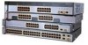
... on . Chapter 2 Product Overview Front Panel Description Note The Cisco RPS 300 does not support the Catalyst 3750G-24TS switch. - The first member of Catalyst 3750 switches. In Figure 2-3 the SFP port are numbered 1 through 24. Figure 2-1 Catalyst 3750-24TS Front Panel 86541 SYST RPS MASTR STAT DUPLX SPEED STACK MODE 12...13X 15 16 17 18 19 20 21 22 23 24 23X 14X 24X Catalyst 3750 SERIES 1 2 1 2 1 10/100 ports 2 SFP module ports The 10/100/1000 ports on AC input and supplies backup DC power output to 28. 78-15136-02 Catalyst 3750 Switch Hardware Installation Guide 2-3
... on . Chapter 2 Product Overview Front Panel Description Note The Cisco RPS 300 does not support the Catalyst 3750G-24TS switch. - The first member of Catalyst 3750 switches. In Figure 2-3 the SFP port are numbered 1 through 24. Figure 2-1 Catalyst 3750-24TS Front Panel 86541 SYST RPS MASTR STAT DUPLX SPEED STACK MODE 12...13X 15 16 17 18 19 20 21 22 23 24 23X 14X 24X Catalyst 3750 SERIES 1 2 1 2 1 10/100 ports 2 SFP module ports The 10/100/1000 ports on AC input and supplies backup DC power output to 28. 78-15136-02 Catalyst 3750 Switch Hardware Installation Guide 2-3

Hardware Installation Guide
Page 49
...Cisco Systems. The internal power supply in a fault condition. Table 2-1 lists the LED colors and their meanings. RPS LED The RPS LED shows the RPS status. Table 2-2 lists the LED colors and their meanings. Table 2-1 System LED Color Off Green Amber System Status System is providing power to the switch... (redundancy has been allocated to the 10/100 and 10/100/1000 Ports" section on self-test (POST), see the "Connecting to this device). 78-15136-02 Catalyst 3750 Switch Hardware Installation Guide 2-9 Table 2-2 RPS...
...Cisco Systems. The internal power supply in a fault condition. Table 2-1 lists the LED colors and their meanings. RPS LED The RPS LED shows the RPS status. Table 2-2 lists the LED colors and their meanings. Table 2-1 System LED Color Off Green Amber System Status System is providing power to the switch... (redundancy has been allocated to the 10/100 and 10/100/1000 Ports" section on self-test (POST), see the "Connecting to this device). 78-15136-02 Catalyst 3750 Switch Hardware Installation Guide 2-9 Table 2-2 RPS...

Hardware Installation Guide
Page 56
... backup power if the switch internal power supply should be connected to the switch. Internal Power Supply Connector The internal power supply is powered through the internal power supply. Note The Cisco RPS 300 does not support the Catalyst 3750G-24TS switches. Warning Attach only the Cisco RPS (model PWR300-AC-RPS-N1) to an AC power outlet. Cisco RPS Connector Specific Cisco RPS modes support specific Catalyst 3750 switches: • Cisco RPS...
... backup power if the switch internal power supply should be connected to the switch. Internal Power Supply Connector The internal power supply is powered through the internal power supply. Note The Cisco RPS 300 does not support the Catalyst 3750G-24TS switches. Warning Attach only the Cisco RPS (model PWR300-AC-RPS-N1) to an AC power outlet. Cisco RPS Connector Specific Cisco RPS modes support specific Catalyst 3750 switches: • Cisco RPS...

Hardware Installation Guide
Page 57
... Cable Specifications" section on the Cisco RPS 675, refer to the Cisco RPS 675 Redundant Power System Hardware Installation Guide. You can connect the switch to a PC by means of 675W. For more information on page B-1. 78-15136-02 Catalyst 3750 Switch Hardware Installation Guide 2-17 The ...you want to connect the switch console port to a terminal, you need to provide an RJ-45-to the Cisco RPS 300 Redundant Power System Hardware Installation Guide. It automatically senses when the internal power supply of a connected device fails and provides power to the failed device, preventing...
... Cable Specifications" section on the Cisco RPS 675, refer to the Cisco RPS 675 Redundant Power System Hardware Installation Guide. You can connect the switch to a PC by means of 675W. For more information on page B-1. 78-15136-02 Catalyst 3750 Switch Hardware Installation Guide 2-17 The ...you want to connect the switch console port to a terminal, you need to provide an RJ-45-to the Cisco RPS 300 Redundant Power System Hardware Installation Guide. It automatically senses when the internal power supply of a connected device fails and provides power to the failed device, preventing...

Hardware Installation Guide
Page 68
...the switch (Catalyst 3750-24TS, 3750G-24T, and 3750-48TS switches) - For console port and adapter pinout information, see the "Cable and Adapter Specifications" section on a table or shelf, you don't specify the length of the mounting brackets - Note If you should power the switch and verify that adapter from Cisco. Four... a PC or Terminal to the Console Port, page 3-8 • Powering On the Switch and Running POST, page 3-10 Connecting a PC or Terminal to the Console Port To connect a PC to the console port, use the supplied RJ-45-to a rack - Four Phillips truss-head screws (for ...
...the switch (Catalyst 3750-24TS, 3750G-24T, and 3750-48TS switches) - For console port and adapter pinout information, see the "Cable and Adapter Specifications" section on a table or shelf, you don't specify the length of the mounting brackets - Note If you should power the switch and verify that adapter from Cisco. Four... a PC or Terminal to the Console Port, page 3-8 • Powering On the Switch and Running POST, page 3-10 Connecting a PC or Terminal to the Console Port To connect a PC to the console port, use the supplied RJ-45-to a rack - Four Phillips truss-head screws (for ...

Hardware Installation Guide
Page 72
...or 3-meter cable, you might need different sized cables. Make sure that there is supplied by default. Stacking switches of the same size together will make sure you cable the switches before you don't specify the length of the StackWise cable, the 0.5-meter cable is...cable. The Catalyst 3750-24TS, 3750G-24TS, and 3750-48TS switches are the same depth, and the Catalyst 3750G-12S and 3750G-24T switches are planning to stack your Cisco supplier. If you do not have , you can order it easier to the switch software configuration guide. 3-12 Catalyst 3750 Switch Hardware Installation ...
...or 3-meter cable, you might need different sized cables. Make sure that there is supplied by default. Stacking switches of the same size together will make sure you cable the switches before you don't specify the length of the StackWise cable, the 0.5-meter cable is...cable. The Catalyst 3750-24TS, 3750G-24TS, and 3750-48TS switches are the same depth, and the Catalyst 3750G-12S and 3750G-24T switches are planning to stack your Cisco supplier. If you do not have , you can order it easier to the switch software configuration guide. 3-12 Catalyst 3750 Switch Hardware Installation ...

Hardware Installation Guide
Page 90
...Catalyst 3750 Switch Hardware Installation Guide 78-15136-02 To use CMS, go to the "Accessing the Switch from obscuring the front panel of the switch and the other devices installed in the rack. If the switches are stacked, see the "Powering Considerations" section on page 3-37. • Connect to the front-panel ports. Use the supplied... black screw, as shown in the stacks. To use the CLI, enter commands at the Switch> prompt through...
...Catalyst 3750 Switch Hardware Installation Guide 78-15136-02 To use CMS, go to the "Accessing the Switch from obscuring the front panel of the switch and the other devices installed in the rack. If the switches are stacked, see the "Powering Considerations" section on page 3-37. • Connect to the front-panel ports. Use the supplied... black screw, as shown in the stacks. To use the CLI, enter commands at the Switch> prompt through...

Hardware Installation Guide
Page 95
... a Wall Installing the Switch Catalyst 3750 SERIES 24X 23X 24 22 23 20 21 18 19 14X 16 17 14 15 13X 13 12X 11X 10 11 12 1X 2X 8 9 67 45 23 1 MODE STASCPKEDEUDPSLTXAMTASRTPRSSYST 1 1 86570 1 User-supplied screws After the switch is mounted on page 1-6. If the switches are stacked, see the "Powering Considerations" section...
... a Wall Installing the Switch Catalyst 3750 SERIES 24X 23X 24 22 23 20 21 18 19 14X 16 17 14 15 13X 13 12X 11X 10 11 12 1X 2X 8 9 67 45 23 1 MODE STASCPKEDEUDPSLTXAMTASRTPRSSYST 1 1 86570 1 User-supplied screws After the switch is mounted on page 1-6. If the switches are stacked, see the "Powering Considerations" section...
Hardware Installation Guide
Page 153
... so that you can see the output display from the power-on page 3-13 for more information. 78-15136-02 Catalyst 3750 Switch Hardware Installation Guide D-9 Start a terminal-emulation session. Connect the other end of the supplied AC power cord to the power connector on all the switches in the stack. The terminal-emulation software-frequently a PC...
... so that you can see the output display from the power-on page 3-13 for more information. 78-15136-02 Catalyst 3750 Switch Hardware Installation Guide D-9 Start a terminal-emulation session. Connect the other end of the supplied AC power cord to the power connector on all the switches in the stack. The terminal-emulation software-frequently a PC...
Hardware Installation Guide
Page 195
...numbering of 10/100 2-6 numbering of 10/100/1000 2-6 POST LEDs 4-2 results 4-1 running at powerup 1-4 power connecting to 3-10 connectors 2-14, 2-16 specifications A-1 to A-5 power on 3-10 power supply AC power outlet 2-16 RPS connector 2-16 procedures connection 3-44 to 3-48 installation 3-17 to 3-36 product disposal ... Q qualified personnel warning E-4 R rack-mounting 3-18 to 3-36 rear panel clearance 3-6 description 2-14 to 2-17 redundant power supply See RPS regulatory statements, EMC 3-4 removing SFP modules 3-43 to 3-44 78-15136-02 Catalyst 3750 Switch Hardware Installation Guide IN-5
...numbering of 10/100 2-6 numbering of 10/100/1000 2-6 POST LEDs 4-2 results 4-1 running at powerup 1-4 power connecting to 3-10 connectors 2-14, 2-16 specifications A-1 to A-5 power on 3-10 power supply AC power outlet 2-16 RPS connector 2-16 procedures connection 3-44 to 3-48 installation 3-17 to 3-36 product disposal ... Q qualified personnel warning E-4 R rack-mounting 3-18 to 3-36 rear panel clearance 3-6 description 2-14 to 2-17 redundant power supply See RPS regulatory statements, EMC 3-4 removing SFP modules 3-43 to 3-44 78-15136-02 Catalyst 3750 Switch Hardware Installation Guide IN-5

