
Installation Guide
Page 2
...BUT ARE PRESENTED WITHOUT WARRANTY OF ANY KIND, EXPRESS OR IMPLIED. These specifications are designed to provide reasonable protection against harmful interference when the equipment is not installed in accordance with Cisco's installation instructions, it off. You can radiate radio-frequency energy and...your right to comply with the limits for a Class B digital device in accordance with radio and television reception. THE SPECIFICATIONS AND INFORMATION REGARDING THE PRODUCTS IN THIS MANUAL ARE SUBJECT TO CHANGE WITHOUT NOTICE. THE SOFTWARE LICENSE AND LIMITED WARRANTY FOR...
...BUT ARE PRESENTED WITHOUT WARRANTY OF ANY KIND, EXPRESS OR IMPLIED. These specifications are designed to provide reasonable protection against harmful interference when the equipment is not installed in accordance with Cisco's installation instructions, it off. You can radiate radio-frequency energy and...your right to comply with the limits for a Class B digital device in accordance with radio and television reception. THE SPECIFICATIONS AND INFORMATION REGARDING THE PRODUCTS IN THIS MANUAL ARE SUBJECT TO CHANGE WITHOUT NOTICE. THE SOFTWARE LICENSE AND LIMITED WARRANTY FOR...

Installation Guide
Page 8
... B-1 1000BaseX Ports B-2 Gigastack Port B-3 Console Port B-3 Cable and Adapter Specifications B-4 Crossover and Straight-Through Cable Pinouts B-4 Rollover Cable and Adapter Pinouts B-5 Identifying a Rollover Cable B-5 Connecting to a PC B-6 Connecting to a Terminal B-7 Translated Safety Warnings C-1 Attaching the Cisco RPS (model PWR600-AC-RPS) C-2 Attaching the Cisco RPS (model PWR300-AC-RPS-N1) C-4 Service Personnel Warning...
... B-1 1000BaseX Ports B-2 Gigastack Port B-3 Console Port B-3 Cable and Adapter Specifications B-4 Crossover and Straight-Through Cable Pinouts B-4 Rollover Cable and Adapter Pinouts B-5 Identifying a Rollover Cable B-5 Connecting to a PC B-6 Connecting to a Terminal B-7 Translated Safety Warnings C-1 Attaching the Cisco RPS (model PWR600-AC-RPS) C-2 Attaching the Cisco RPS (model PWR300-AC-RPS-N1) C-4 Service Personnel Warning...

Installation Guide
Page 12
...translations in various languages of how the switch could be used to connect to the switch. Chapter 2, "Installing and Starting Up the Switch," contains the procedures for the switches and the regulatory agency approvals. Appendix B, "Connector and Cable Specifications," describes the connectors, cables, and adapters... are in boldface. • Arguments for which you are installing the switch. It describes the switch ports, the standards they support, and the switch LEDs. Examples of the warnings in this guide. Catalyst 3500 Series XL Hardware Installation Guide xii 78-6456-04
...translations in various languages of how the switch could be used to connect to the switch. Chapter 2, "Installing and Starting Up the Switch," contains the procedures for the switches and the regulatory agency approvals. Appendix B, "Connector and Cable Specifications," describes the connectors, cables, and adapters... are in boldface. • Arguments for which you are installing the switch. It describes the switch ports, the standards they support, and the switch LEDs. Examples of the warnings in this guide. Catalyst 3500 Series XL Hardware Installation Guide xii 78-6456-04

Installation Guide
Page 25
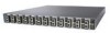
... switches. A feature specific to the Catalyst 3524-PWR XL switch is its ability to provide inline power to Cisco IP Phones. (Phone adapters are not required when connecting to the Catalyst 3524-PWR XL 10/100 switch ports.) Figure 1-1 shows the switch models in different network topologies Features The Catalyst 3500 series XL switches-also referred to as Catalyst 3500 XL switches...
... switches. A feature specific to the Catalyst 3524-PWR XL switch is its ability to provide inline power to Cisco IP Phones. (Phone adapters are not required when connecting to the Catalyst 3524-PWR XL 10/100 switch ports.) Figure 1-1 shows the switch models in different network topologies Features The Catalyst 3500 series XL switches-also referred to as Catalyst 3500 XL switches...

Installation Guide
Page 32
...These ports also can be connected to the following phones: Cisco IP Phone 7960, Cisco IP Phone 7940, and Cisco IP Phone 7910 • Automatically detect if a Cisco IP Phone is connected. The Catalyst 3548 and 3524-PWR XL switches also support per -port basis, you select the Auto setting... operating at 100 Mbps. If the connected device also supports autonegotiation, the switch port negotiates the best connection (that is, the fastest line speed that the cable is required for each 10/100 port: Auto and Never. Refer to operate in Appendix B, "Connector and Cable Specifications."
...These ports also can be connected to the following phones: Cisco IP Phone 7960, Cisco IP Phone 7940, and Cisco IP Phone 7910 • Automatically detect if a Cisco IP Phone is connected. The Catalyst 3548 and 3524-PWR XL switches also support per -port basis, you select the Auto setting... operating at 100 Mbps. If the connected device also supports autonegotiation, the switch port negotiates the best connection (that is, the fastest line speed that the cable is required for each 10/100 port: Auto and Never. Refer to operate in Appendix B, "Connector and Cable Specifications."

Installation Guide
Page 47
..., use up to 150W DC each. Cisco RPS Connector Specific Cisco RPS models support specific Catalyst 3500 XL switches: • Cisco RPS 600 (model PWR600-AC-RPS)-Supports the Catalyst 3512, 3524, 3548, and 3508 XL switches • Cisco RPS 300 (model PWR300-AC-RPS)-Supports the Catalyst 3524-PWR XL switch RPS Connector on the Catalyst 3508, 3512, 3524, and 3548 XL...
..., use up to 150W DC each. Cisco RPS Connector Specific Cisco RPS models support specific Catalyst 3500 XL switches: • Cisco RPS 600 (model PWR600-AC-RPS)-Supports the Catalyst 3512, 3524, 3548, and 3508 XL switches • Cisco RPS 300 (model PWR300-AC-RPS)-Supports the Catalyst 3524-PWR XL switch RPS Connector on the Catalyst 3508, 3512, 3524, and 3548 XL...

Installation Guide
Page 48
... Adapter Specifications" section on page B-4. It provides a fully-redundant power source for these applications. 1-24 Catalyst 3500 Series XL Hardware Installation Guide 78-6456-04 Although it can connect a Catalyst 3500 XL switch to a PC by means of the switches has experienced power failure and automatically sends power to six switches, it supports up to the Cisco...
... Adapter Specifications" section on page B-4. It provides a fully-redundant power source for these applications. 1-24 Catalyst 3500 Series XL Hardware Installation Guide 78-6456-04 Although it can connect a Catalyst 3500 XL switch to a PC by means of the switches has experienced power failure and automatically sends power to six switches, it supports up to the Cisco...

Installation Guide
Page 65
.... • Operating environment is within the ranges listed in Appendix A, "Technical Specifications." 78-6456-04 Catalyst 3500 Series XL Hardware Installation Guide 2-7 Statement 256 Installation Guidelines When determining where to place the switch, be used . Chapter 2 Installing and Starting Up the Switch Hungary Preparing for which special conditions of installation and protection distance are...
.... • Operating environment is within the ranges listed in Appendix A, "Technical Specifications." 78-6456-04 Catalyst 3500 Series XL Hardware Installation Guide 2-7 Statement 256 Installation Guidelines When determining where to place the switch, be used . Chapter 2 Installing and Starting Up the Switch Hungary Preparing for which special conditions of installation and protection distance are...

Installation Guide
Page 81
For console port and adapter pinout information, see the "Cable and Adapter Specifications" section on the GigaStack GBIC connections and configuration scenarios, see the Catalyst GigaStack Gigabit Interface Converter Hardware Installation Guide. Follow these console port default characteristics: • ...No parity After you have gained access to the switch, you want to connect the switch console port to a terminal. See the Cisco IOS Desktop Switching Software Configuration Guide for instructions. 78-6456-04 Catalyst 3500 Series XL Hardware Installation Guide 2-23 The terminal...
For console port and adapter pinout information, see the "Cable and Adapter Specifications" section on the GigaStack GBIC connections and configuration scenarios, see the Catalyst GigaStack Gigabit Interface Converter Hardware Installation Guide. Follow these console port default characteristics: • ...No parity After you have gained access to the switch, you want to connect the switch console port to a terminal. See the Cisco IOS Desktop Switching Software Configuration Guide for instructions. 78-6456-04 Catalyst 3500 Series XL Hardware Installation Guide 2-23 The terminal...

Installation Guide
Page 84
...Cisco. Enter the switch IP address, and press Return: Enter IP address: ip_address Enter the subnet mask (IP netmask) address, and press Return: Enter IP netmask: ip_netmask Enter Y to specify a default gateway (router): Would you want to connect the switch... create an initial configuration for the switch, and press Return: 2-26 Catalyst 3500 Series XL Hardware Installation Guide ...Specifications" section on page B-4. Use the supplied rollover cable and DB-9 adapter to connect a PC to restart the setup program. Assigning Switch Information Chapter 2 Installing and Starting Up the Switch...
...Cisco. Enter the switch IP address, and press Return: Enter IP address: ip_address Enter the subnet mask (IP netmask) address, and press Return: Enter IP netmask: ip_netmask Enter Y to specify a default gateway (router): Would you want to connect the switch... create an initial configuration for the switch, and press Return: 2-26 Catalyst 3500 Series XL Hardware Installation Guide ...Specifications" section on page B-4. Use the supplied rollover cable and DB-9 adapter to connect a PC to restart the setup program. Assigning Switch Information Chapter 2 Installing and Starting Up the Switch...

Installation Guide
Page 97
...-6456-04 Table A-1, Table A-2, and Table A-3, list the technical specifications for the Catalyst 3508G XL Switch Environmental Ranges Operating temperature Storage temperature Operating humidity Operating altitude Storage altitude Power Requirements AC input voltage DC input voltages Power consumption ...@14A, +12V @3A 82.2W 280 Btus per hour 12 lb (5.45 kg) 1.75 x 16 x 17.5 in. (4.45 x 40.46 x 44.45 cm) Catalyst 3500 Series XL Hardware Installation Guide A-1 Table A-1 Technical Specifications for the Catalyst 3500 series XL switches. Table A-4 lists the regulatory agency approvals.
...-6456-04 Table A-1, Table A-2, and Table A-3, list the technical specifications for the Catalyst 3508G XL Switch Environmental Ranges Operating temperature Storage temperature Operating humidity Operating altitude Storage altitude Power Requirements AC input voltage DC input voltages Power consumption ...@14A, +12V @3A 82.2W 280 Btus per hour 12 lb (5.45 kg) 1.75 x 16 x 17.5 in. (4.45 x 40.46 x 44.45 cm) Catalyst 3500 Series XL Hardware Installation Guide A-1 Table A-1 Technical Specifications for the Catalyst 3500 series XL switches. Table A-4 lists the regulatory agency approvals.

Installation Guide
Page 98
Appendix A Technical Specifications Table A-2 Technical Specifications for the Catalyst 3512, 3524, and 3548 XL Switches Catalyst 3512 XL Catalyst 3524 XL Catalyst 3548 XL Environmental Ranges Operating temperature 32 to 113°F (0 to 45°C) 32 to 113°F (0 to 45°C) 32 to 113°F (0 to ....82 x 17.5 in. 1.73 x 15.34 x 17.5 in D x W) (4.45 x 30.02 x 44.45 cm) (4.45 x 30.02 x 44.45 cm) (4.39 x 39.0 x 44.45 cm) Catalyst 3500 Series XL Hardware Installation Guide A-2 78-6456-04
Appendix A Technical Specifications Table A-2 Technical Specifications for the Catalyst 3512, 3524, and 3548 XL Switches Catalyst 3512 XL Catalyst 3524 XL Catalyst 3548 XL Environmental Ranges Operating temperature 32 to 113°F (0 to 45°C) 32 to 113°F (0 to 45°C) 32 to 113°F (0 to ....82 x 17.5 in. 1.73 x 15.34 x 17.5 in D x W) (4.45 x 30.02 x 44.45 cm) (4.45 x 30.02 x 44.45 cm) (4.39 x 39.0 x 44.45 cm) Catalyst 3500 Series XL Hardware Installation Guide A-2 78-6456-04

Installation Guide
Page 99
Appendix A Technical Specifications Table A-3 Technical Specifications for the Catalyst 3524-PWR XL Switch Environmental Ranges Operating temperature 32 to 113°F (0 to 45°C) Storage temperature -4 to 149°F (-10 to 65°C) Operating humidity 10 to 85% (... Power consumption 100 to 127/200 to 240 VAC (autoranging) 50 to NOM-019-SCFI CE Marking CE Marking 78-6456-04 Catalyst 3500 Series XL Hardware Installation Guide A-3 Table A-4 Catalyst 3500 Series XL Agency Approvals Safety EMC UL to UL 1950, Third Edition FCC Part 15 Class A c-UL to CAN/CSA...
Appendix A Technical Specifications Table A-3 Technical Specifications for the Catalyst 3524-PWR XL Switch Environmental Ranges Operating temperature 32 to 113°F (0 to 45°C) Storage temperature -4 to 149°F (-10 to 65°C) Operating humidity 10 to 85% (... Power consumption 100 to 127/200 to 240 VAC (autoranging) 50 to NOM-019-SCFI CE Marking CE Marking 78-6456-04 Catalyst 3500 Series XL Hardware Installation Guide A-3 Table A-4 Catalyst 3500 Series XL Agency Approvals Safety EMC UL to UL 1950, Third Edition FCC Part 15 Class A c-UL to CAN/CSA...

Installation Guide
Page 100
Appendix A Technical Specifications Catalyst 3500 Series XL Hardware Installation Guide A-4 78-6456-04
Appendix A Technical Specifications Catalyst 3500 Series XL Hardware Installation Guide A-4 78-6456-04

Installation Guide
Page 101
... you use a crossover cable. (Figure B-4 illustrates the crossover cable schematics.) Note Use a straight-through cable to compatible workstations, servers, routers, and Cisco IP Phones, you must use a straight-through cable wired for 10BaseT and 100BaseTX (Figure B-5 illustrates the straight-through cable and adapter can be attached...one of the ports is designated with internal crossovers, as indicated by an X in the port name. APPENDIX B Connector and Cable Specifications This appendix describes the Catalyst 3500 XL switch ports and the cables and adapters that you use to connect the...
... you use a crossover cable. (Figure B-4 illustrates the crossover cable schematics.) Note Use a straight-through cable to compatible workstations, servers, routers, and Cisco IP Phones, you must use a straight-through cable wired for 10BaseT and 100BaseTX (Figure B-5 illustrates the straight-through cable and adapter can be attached...one of the ports is designated with internal crossovers, as indicated by an X in the port name. APPENDIX B Connector and Cable Specifications This appendix describes the Catalyst 3500 XL switch ports and the cables and adapters that you use to connect the...

Installation Guide
Page 102
Connector Specifications Appendix B Connector and Cable Specifications Figure B-1 10/100 Port Pinouts Pin Label 1 RD+ 2 RD- 3 TD+ 4 NC 5 NC 6 TD- 7 NC 8 NC 12345678 H5318 1000BaseX Ports 1000BaseX ports use duplex SC connectors, as shown in Figure B-2. Figure B-2 1000BaseX SC Connector H8707 Tx Rx Catalyst 3500 Series XL Hardware Installation Guide B-2 78-6456-04
Connector Specifications Appendix B Connector and Cable Specifications Figure B-1 10/100 Port Pinouts Pin Label 1 RD+ 2 RD- 3 TD+ 4 NC 5 NC 6 TD- 7 NC 8 NC 12345678 H5318 1000BaseX Ports 1000BaseX ports use duplex SC connectors, as shown in Figure B-2. Figure B-2 1000BaseX SC Connector H8707 Tx Rx Catalyst 3500 Series XL Hardware Installation Guide B-2 78-6456-04

Installation Guide
Page 103
... used to connect the console port of the switch to a console PC. The supplied RJ-45-to a terminal. For console port and adapter pinout information, see Table B-1 and Table B-2. 78-6456-04 Catalyst 3500 Series XL Hardware Installation Guide B-3 Caution...-45 connector, described in Figure B-3. You can order a kit (part number ACS-DSBUASYN=) containing that adapter from Cisco. Appendix B Connector and Cable Specifications Connector Specifications Gigastack Port The GigaStack Gigabit Interface Converter (GBIC) uses proprietary connectors, as shown in Table B-1 and Table B-2. ...
... used to connect the console port of the switch to a console PC. The supplied RJ-45-to a terminal. For console port and adapter pinout information, see Table B-1 and Table B-2. 78-6456-04 Catalyst 3500 Series XL Hardware Installation Guide B-3 Caution...-45 connector, described in Figure B-3. You can order a kit (part number ACS-DSBUASYN=) containing that adapter from Cisco. Appendix B Connector and Cable Specifications Connector Specifications Gigastack Port The GigaStack Gigabit Interface Converter (GBIC) uses proprietary connectors, as shown in Table B-1 and Table B-2. ...

Installation Guide
Page 104
Switch 3 RD+ 6 RD- 1 RD+ 2 RD- 1 TD+ 2 TD- Cable and Adapter Specifications Appendix B Connector and Cable Specifications Cable and Adapter Specifications Crossover and Straight-Through Cable Pinouts The schematics of crossover and straight-through cables are shown in Figure B-4 and Figure B-5. H5579 Figure B-5 Straight-Through Cable Schematic Switch 3 TD+ 6 TD- Switch 3 TD+ 6 TD- 1 RD+ 2 RD- 1 RD+ 2 RD- Figure B-4 Crossover Cable Schematic Switch 3 TD+ 6 TD- H5578 Catalyst 3500 Series XL Hardware Installation Guide B-4 78-6456-04
Switch 3 RD+ 6 RD- 1 RD+ 2 RD- 1 TD+ 2 TD- Cable and Adapter Specifications Appendix B Connector and Cable Specifications Cable and Adapter Specifications Crossover and Straight-Through Cable Pinouts The schematics of crossover and straight-through cables are shown in Figure B-4 and Figure B-5. H5579 Figure B-5 Straight-Through Cable Schematic Switch 3 TD+ 6 TD- Switch 3 TD+ 6 TD- 1 RD+ 2 RD- 1 RD+ 2 RD- Figure B-4 Crossover Cable Schematic Switch 3 TD+ 6 TD- H5578 Catalyst 3500 Series XL Hardware Installation Guide B-4 78-6456-04

Installation Guide
Page 105
... outside of the right plug (see Figure B-6). Pin 8 H10632 78-6456-04 Catalyst 3500 Series XL Hardware Installation Guide B-5 The wire connected to the pin on the outside of the cable. Appendix B Connector and Cable Specifications Cable and Adapter Specifications Rollover Cable and Adapter Pinouts Identifying a Rollover Cable To identify a rollover cable, compare...
... outside of the right plug (see Figure B-6). Pin 8 H10632 78-6456-04 Catalyst 3500 Series XL Hardware Installation Guide B-5 The wire connected to the pin on the outside of the cable. Appendix B Connector and Cable Specifications Cable and Adapter Specifications Rollover Cable and Adapter Pinouts Identifying a Rollover Cable To identify a rollover cable, compare...

Installation Guide
Page 106
... 5 3 4 7 Console Device Signal CTS DSR RxD GND GND TxD DTR RTS Catalyst 3500 Series XL Hardware Installation Guide B-6 78-6456-04 Figure B-7 Connecting the Console Port to a PC PC Catalyst 3500 series XL switch 22003 RJ-45-to-RJ-45 rollover cable RJ-45-to-DB-9 adapter (labeled ...Not connected 2 7 TxD 3 6 GND 4 5 GND 5 4 RxD 6 3 Not connected 7 2 CTS 8 1 RJ-45-to a PC. Cable and Adapter Specifications Appendix B Connector and Cable Specifications Connecting to a PC Use the supplied thin, flat, RJ-45-to-RJ-45 rollover cable and RJ-45-to-DB-9 female DTE adapter...
... 5 3 4 7 Console Device Signal CTS DSR RxD GND GND TxD DTR RTS Catalyst 3500 Series XL Hardware Installation Guide B-6 78-6456-04 Figure B-7 Connecting the Console Port to a PC PC Catalyst 3500 series XL switch 22003 RJ-45-to-RJ-45 rollover cable RJ-45-to-DB-9 adapter (labeled ...Not connected 2 7 TxD 3 6 GND 4 5 GND 5 4 RxD 6 3 Not connected 7 2 CTS 8 1 RJ-45-to a PC. Cable and Adapter Specifications Appendix B Connector and Cable Specifications Connecting to a PC Use the supplied thin, flat, RJ-45-to-RJ-45 rollover cable and RJ-45-to-DB-9 female DTE adapter...