Hardware Installation Guide
Page 2
... you may result in the equipment no longer complying with the limits for a Class B digital device in accordance with the specifications in a particular installation. Catalyst 3560 Switch Hardware Installation Guide © 2004-2010 Cisco Systems, Inc. USERS MUST TAKE FULL RESPONSIBILITY FOR THEIR APPLICATION OF ANY PRODUCTS. If it may cause interference with the...
... you may result in the equipment no longer complying with the limits for a Class B digital device in accordance with the specifications in a particular installation. Catalyst 3560 Switch Hardware Installation Guide © 2004-2010 Cisco Systems, Inc. USERS MUST TAKE FULL RESPONSIBILITY FOR THEIR APPLICATION OF ANY PRODUCTS. If it may cause interference with the...

Hardware Installation Guide
Page 6
... and 10/100/1000 Ports B-1 SFP Module Ports B-2 Dual-Purpose Ports B-3 Console Port B-3 Cable and Adapter Specifications B-4 SFP Module Cable Specifications B-4 Two Twisted-Pair Cable Pinouts B-5 Four Twisted-Pair Cable Pinouts for 1000BASE-T Ports B-6 Identifying a Crossover Cable... to DC Power C-1 Connecting to DC Power C-1 Preparing for Installation C-2 Grounding the Switch C-2 Wiring the DC-Input Power Source C-5 Configuring the Switch with the CLI-Based Setup Program D-1 Preparing for Setup D-1 Completing the Setup Program D-3 Catalyst 3560 Switch Hardware Installation Guide vi OL-6337-07
... and 10/100/1000 Ports B-1 SFP Module Ports B-2 Dual-Purpose Ports B-3 Console Port B-3 Cable and Adapter Specifications B-4 SFP Module Cable Specifications B-4 Two Twisted-Pair Cable Pinouts B-5 Four Twisted-Pair Cable Pinouts for 1000BASE-T Ports B-6 Identifying a Crossover Cable... to DC Power C-1 Connecting to DC Power C-1 Preparing for Installation C-2 Grounding the Switch C-2 Wiring the DC-Input Power Source C-5 Configuring the Switch with the CLI-Based Setup Program D-1 Preparing for Setup D-1 Completing the Setup Program D-3 Catalyst 3560 Switch Hardware Installation Guide vi OL-6337-07

Hardware Installation Guide
Page 19
... documentation that came with IEEE 802.3af and Cisco prestandard PoE support for Cisco IP Phones and Cisco Aironet Access Points. • Each of the Catalyst 3560-8PC, 3560-12PC-S, 3560-24PS, and 3560V2-24PS switch 10/100 ports or the Catalyst 3560G-24PS switch 10/100/1000 ports deliver up to a ...described in Appendix B, "Connector and Cable Specifications." • You can use the mdix auto interface configuration command to enable the automatic medium-dependent interface crossover (auto-MDIX) feature. On the Catalyst 3560-48PS, 3560G-48PS, and 3560V2-48PS switches, any 24 of the 48 10/...
... documentation that came with IEEE 802.3af and Cisco prestandard PoE support for Cisco IP Phones and Cisco Aironet Access Points. • Each of the Catalyst 3560-8PC, 3560-12PC-S, 3560-24PS, and 3560V2-24PS switch 10/100 ports or the Catalyst 3560G-24PS switch 10/100/1000 ports deliver up to a ...described in Appendix B, "Connector and Cable Specifications." • You can use the mdix auto interface configuration command to enable the automatic medium-dependent interface crossover (auto-MDIX) feature. On the Catalyst 3560-48PS, 3560G-48PS, and 3560V2-48PS switches, any 24 of the 48 10/...

Hardware Installation Guide
Page 20
...shows the status of the SFP module port. Front Panel Description Chapter 1 Product Overview Many legacy powered devices, including older Cisco IP phones and access points that first links up. For more information about configuring speed and duplex settings for your SFP ... port is on page 2-18 for the active connector. 1-10 Catalyst 3560 Switch Hardware Installation Guide OL-6337-07 The dual front ends are field-replaceable, providing uplink interfaces when inserted in the "SFP Module Cable Specifications" section on page B-4. For information about using the SFP module patch...
...shows the status of the SFP module port. Front Panel Description Chapter 1 Product Overview Many legacy powered devices, including older Cisco IP phones and access points that first links up. For more information about configuring speed and duplex settings for your SFP ... port is on page 2-18 for the active connector. 1-10 Catalyst 3560 Switch Hardware Installation Guide OL-6337-07 The dual front ends are field-replaceable, providing uplink interfaces when inserted in the "SFP Module Cable Specifications" section on page B-4. For information about using the SFP module patch...

Hardware Installation Guide
Page 29
..., you need to provide an RJ-45-to the switch. For complete information about the Cisco RPS products, including compatibility matrixes listing the supported RPS for each Catalyst 3560 switch, see the "Connector and Cable Specifications" section on the installed power-supply modules. Cisco RPS 675 The Cisco 675 RPS is not Network Equipment Building Systems (NEBS...
..., you need to provide an RJ-45-to the switch. For complete information about the Cisco RPS products, including compatibility matrixes listing the supported RPS for each Catalyst 3560 switch, see the "Connector and Cable Specifications" section on the installed power-supply modules. Cisco RPS 675 The Cisco 675 RPS is not Network Equipment Building Systems (NEBS...

Hardware Installation Guide
Page 37
... grounding architecture of this product is within the ranges listed in Appendix A, "Technical Specifications." • Airflow around the switch and through the vents is sufficient for the Catalyst 3560 switch. If the switch is installed in Table B-1 on page B-4, which lists the cable specifications for 1000BASE-X and 100BASE-X SFP modules for unrestricted cabling. - Make sure the...
... grounding architecture of this product is within the ranges listed in Appendix A, "Technical Specifications." • Airflow around the switch and through the vents is sufficient for the Catalyst 3560 switch. If the switch is installed in Table B-1 on page B-4, which lists the cable specifications for 1000BASE-X and 100BASE-X SFP modules for unrestricted cabling. - Make sure the...
Hardware Installation Guide
Page 47
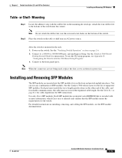
... the dust covers on them for reliable communications, the cable must match the wave-length specifications on the table or shelf near the corners. Each SFP module has an internal serial EEPROM... or Shelf- Step 2 Place the switch on the other end of the cable, and for protection. See the Catalyst 3560 Switch Getting Started Guide for the list of the switch near an AC power source. You... recessed screw holes on the switch. After the switch is encoded with the rubber feet in the rack: 1. Connect to the bottom of supported SFP modules. Use only Cisco SFP modules. Note When the...
... the dust covers on them for reliable communications, the cable must match the wave-length specifications on the table or shelf near the corners. Each SFP module has an internal serial EEPROM... or Shelf- Step 2 Place the switch on the other end of the cable, and for protection. See the Catalyst 3560 Switch Getting Started Guide for the list of the switch near an AC power source. You... recessed screw holes on the switch. After the switch is encoded with the rubber feet in the rack: 1. Connect to the bottom of supported SFP modules. Use only Cisco SFP modules. Note When the...
Hardware Installation Guide
Page 52
and 48-Port Switches) The Catalyst 3560 switch can connect to a Cisco IP Phone through a straight-through cable to an RJ-45 connector on the front panel. (See Figure 2-18.) When connecting to switches or repeaters, use a crossover cable. (See the "Cable and Adapter Specifications" section on page B-4 for solutions to the switch. Use the LAN-to-phone...
and 48-Port Switches) The Catalyst 3560 switch can connect to a Cisco IP Phone through a straight-through cable to an RJ-45 connector on the front panel. (See Figure 2-18.) When connecting to switches or repeaters, use a crossover cable. (See the "Cable and Adapter Specifications" section on page B-4 for solutions to the switch. Use the LAN-to-phone...
Hardware Installation Guide
Page 53
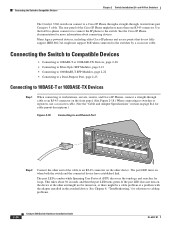
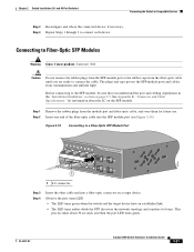
.... Before connecting to the SFP module, be sure that you are ready to connect the cable. See Appendix B, "Connector and Cable Specifications," for loops. Chapter 2 Switch Installation (24- Step 2 Insert one end of the fiber-optic cable into a fiber-optic connector on a target device. Figure ... This process takes about the LC on page 2-5. Connecting to connect each device. and 48-Port Switches) Connecting the Switch to a Fiber-Optic SFP Module Port 40 41 42 43 44 45 46 47 48 47X Catalyst 3560 SERIES PoE-48 1 3 48X 2 4 1 97931 1 LC connector Step 3 Step ...
.... Before connecting to the SFP module, be sure that you are ready to connect the cable. See Appendix B, "Connector and Cable Specifications," for loops. Chapter 2 Switch Installation (24- Step 2 Insert one end of the fiber-optic cable into a fiber-optic connector on a target device. Figure ... This process takes about the LC on page 2-5. Connecting to connect each device. and 48-Port Switches) Connecting the Switch to a Fiber-Optic SFP Module Port 40 41 42 43 44 45 46 47 48 47X Catalyst 3560 SERIES PoE-48 1 3 48X 2 4 1 97931 1 LC connector Step 3 Step ...

Hardware Installation Guide
Page 57
...; Where to Go Next, page 3-20 For information about connecting to the switch, see Chapter 2, "Switch Installation (24- For installing the other Catalyst 3560 switches, see the "Connecting the Switch to the Catalyst 3560-8PC and Catalyst 3560-12PC-S switches. Note This chapter describes the installation information specific to Compatible Devices" section on self-test (POST) that ensures proper...
...; Where to Go Next, page 3-20 For information about connecting to the switch, see Chapter 2, "Switch Installation (24- For installing the other Catalyst 3560 switches, see the "Connecting the Switch to the Catalyst 3560-8PC and Catalyst 3560-12PC-S switches. Note This chapter describes the installation information specific to Compatible Devices" section on self-test (POST) that ensures proper...
Hardware Installation Guide
Page 61
...°F (45°C) and is unrestricted. Chapter 3 Switch Installation (8- Allow at least 3 inches (7.6 cm) of clearance on the top of clearance above each switch in Appendix A, "Technical Specifications." • Airflow around the switch and through the vents is in an environment that - ...Clearance to the nearest rack metal hardware. According to intrabuilding or nonexposed wiring or cabling. OL-6337-07 Catalyst 3560 Switch Hardware Installation Guide 3-5 If the switch is installed in a closed or multirack assembly). • No other items are placed on all sides and...
...°F (45°C) and is unrestricted. Chapter 3 Switch Installation (8- Allow at least 3 inches (7.6 cm) of clearance on the top of clearance above each switch in Appendix A, "Technical Specifications." • Airflow around the switch and through the vents is in an environment that - ...Clearance to the nearest rack metal hardware. According to intrabuilding or nonexposed wiring or cabling. OL-6337-07 Catalyst 3560 Switch Hardware Installation Guide 3-5 If the switch is installed in a closed or multirack assembly). • No other items are placed on all sides and...
Hardware Installation Guide
Page 62
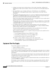
...the chassis, which can order, RCKMNT-19-CMPCT=. When the fiber-optic cable span is not included but which lists the cable specifications for 1000BASE-X and 100BASE-X SFP modules for this equipment in the link to -DB-25 female DTE adapter. Cable locks are ...Catalyst 3560 switch. Catalyst 3560-8PC switch-8 10/100 PoE ports and 1 dual-purpose port (one 10/100/1000BASE-T copper port and one SFP module slot) Equipment That You Supply You need to provide an RJ-45-to avoid overloading the receiver. To order a cable guard (CBLGRD-C3560-12PC or CBLGRD-C3560-8PC), contact your Cisco...
...the chassis, which can order, RCKMNT-19-CMPCT=. When the fiber-optic cable span is not included but which lists the cable specifications for 1000BASE-X and 100BASE-X SFP modules for this equipment in the link to -DB-25 female DTE adapter. Cable locks are ...Catalyst 3560 switch. Catalyst 3560-8PC switch-8 10/100 PoE ports and 1 dual-purpose port (one 10/100/1000BASE-T copper port and one SFP module slot) Equipment That You Supply You need to provide an RJ-45-to avoid overloading the receiver. To order a cable guard (CBLGRD-C3560-12PC or CBLGRD-C3560-8PC), contact your Cisco...
Hardware Installation Guide
Page 79
..., good module. OL-6337-07 Catalyst 3560 Switch Hardware Installation Guide 4-3 Link Status Verify that both ends of supported SFP modules. • Use the show link, but is not. See Appendix B, "Connector and Cable Specifications." Transceiver Module Port Issues Use only Cisco small form-factor (SFP) modules... on page 1-1 for a list of the cable are using the correct cable type. This encoding provides a way for Cisco to be seated, but the other side...
..., good module. OL-6337-07 Catalyst 3560 Switch Hardware Installation Guide 4-3 Link Status Verify that both ends of supported SFP modules. • Use the show link, but is not. See Appendix B, "Connector and Cable Specifications." Transceiver Module Port Issues Use only Cisco small form-factor (SFP) modules... on page 1-1 for a list of the cable are using the correct cable type. This encoding provides a way for Cisco to be seated, but the other side...
Hardware Installation Guide
Page 81
...). See Appendix B, "Connector and Cable Specifications," for the ports on both sides of the connection. • If a remote device does not autonegotiate, configure the duplex settings on the connected port. • A port is set to manually set both ends of the connection. OL-6337-07 Catalyst 3560 Switch Hardware Installation Guide 4-5 To troubleshoot...
...). See Appendix B, "Connector and Cable Specifications," for the ports on both sides of the connection. • If a remote device does not autonegotiate, configure the duplex settings on the connected port. • A port is set to manually set both ends of the connection. OL-6337-07 Catalyst 3560 Switch Hardware Installation Guide 4-5 To troubleshoot...
Hardware Installation Guide
Page 85
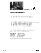
...-24PS Switch • Table A-3 on page A-2, Specifications for the Catalyst 3560-48PS Switch • Table A-4 on page A-3, Specifications for the Catalyst 3560-24TS-S Switch • Table A-5 on page A-3, Specifications for the Catalyst 3560-48TS-S Switch • Table A-6 on page A-3, Specifications for the Catalyst 3560-8PC and Catalyst 3560-12PC Switches • Table A-7 on page A-4, Specifications for the Catalyst 3560G-24TS Switch • Table A-8 on page A-4, Specifications for the Catalyst 3560G-24PS Switch...
...-24PS Switch • Table A-3 on page A-2, Specifications for the Catalyst 3560-48PS Switch • Table A-4 on page A-3, Specifications for the Catalyst 3560-24TS-S Switch • Table A-5 on page A-3, Specifications for the Catalyst 3560-48TS-S Switch • Table A-6 on page A-3, Specifications for the Catalyst 3560-8PC and Catalyst 3560-12PC Switches • Table A-7 on page A-4, Specifications for the Catalyst 3560G-24TS Switch • Table A-8 on page A-4, Specifications for the Catalyst 3560G-24PS Switch...
Hardware Installation Guide
Page 86
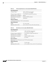
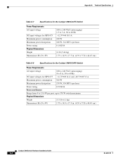
Appendix A Technical Specifications Table A-2 Technical Specifications for the Catalyst 3560-24PS Switch Power Requirements AC input voltage 100 to 240 VAC (autoranging) 5.5 A to 2.8 A, 50 to 60 Hz DC input voltage for RPS 675 +12 V @7.5 A and -48 V @7.8 A... Physical Dimensions Weight 11.3 lb (5.14 kg) Dimensions (H x D x W) 1.73 x 11.81 x 17.5 in. (4.39 x 30 x 44.45 cm) Table A-3 Specifications for the Catalyst 3560-48PS Switch Power Requirements AC input voltage 100 to 240 VAC (autoranging) 5.5 to 2.8 A, 50 to 60 Hz DC input voltages for RPS 675 +12 V @7.5 A and -48 V @7.8 A...
Appendix A Technical Specifications Table A-2 Technical Specifications for the Catalyst 3560-24PS Switch Power Requirements AC input voltage 100 to 240 VAC (autoranging) 5.5 A to 2.8 A, 50 to 60 Hz DC input voltage for RPS 675 +12 V @7.5 A and -48 V @7.8 A... Physical Dimensions Weight 11.3 lb (5.14 kg) Dimensions (H x D x W) 1.73 x 11.81 x 17.5 in. (4.39 x 30 x 44.45 cm) Table A-3 Specifications for the Catalyst 3560-48PS Switch Power Requirements AC input voltage 100 to 240 VAC (autoranging) 5.5 to 2.8 A, 50 to 60 Hz DC input voltages for RPS 675 +12 V @7.5 A and -48 V @7.8 A...
Hardware Installation Guide
Page 87
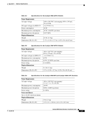
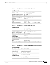
... 0.075 KVA 8.5 lb (3.9 kg) 1.73 x 11.81 x 17.5 in. (4.39 x 30 x 44.45 cm) Table A-5 Specifications for the Catalyst 3560-48TS-S Switch Power Requirements AC input voltage DC input voltages for RPS 675 Maximum power consumption Maximum power dissipation Power rating Physical Dimensions Weight Dimensions...hour 0.110 KVA 9.1 lb (4.1 kg) 1.73 x 11.81 x 17.5 in. (4.39 x 30 x 44.45 cm) Table A-6 Specifications for the Catalyst 3560-8PC and Catalyst 3560-12PC Switches Power Requirements AC input voltage Maximum power consumption Maximum power dissipation Power rating Power over Ethernet Up to 124...
... 0.075 KVA 8.5 lb (3.9 kg) 1.73 x 11.81 x 17.5 in. (4.39 x 30 x 44.45 cm) Table A-5 Specifications for the Catalyst 3560-48TS-S Switch Power Requirements AC input voltage DC input voltages for RPS 675 Maximum power consumption Maximum power dissipation Power rating Physical Dimensions Weight Dimensions...hour 0.110 KVA 9.1 lb (4.1 kg) 1.73 x 11.81 x 17.5 in. (4.39 x 30 x 44.45 cm) Table A-6 Specifications for the Catalyst 3560-8PC and Catalyst 3560-12PC Switches Power Requirements AC input voltage Maximum power consumption Maximum power dissipation Power rating Power over Ethernet Up to 124...
Hardware Installation Guide
Page 88
Appendix A Technical Specifications Table A-7 Specifications for the Catalyst 3560G-24TS Switch Power Requirements AC input voltage DC input voltages for RPS 675 Maximum power consumption Maximum power dissipation Power rating Physical Dimensions Weight Dimensions (H x D x W) 100 to... V @10.5 A 100 W 100 W, 314 BTUs per hour 0.10 KVA 12 lb (5.44 kg) 1.73 x 14.9 x 17.5 in. (4.39 x 37.8 x 44.45 cm) Table A-8 Specifications for the Catalyst 3560G-24PS Switch Power Requirements AC input voltage 100 to 240 VAC (autoranging) 4 to 8 A, 50 to 60 Hz DC input voltages for RPS 675 +12 V @14 A and...
Appendix A Technical Specifications Table A-7 Specifications for the Catalyst 3560G-24TS Switch Power Requirements AC input voltage DC input voltages for RPS 675 Maximum power consumption Maximum power dissipation Power rating Physical Dimensions Weight Dimensions (H x D x W) 100 to... V @10.5 A 100 W 100 W, 314 BTUs per hour 0.10 KVA 12 lb (5.44 kg) 1.73 x 14.9 x 17.5 in. (4.39 x 37.8 x 44.45 cm) Table A-8 Specifications for the Catalyst 3560G-24PS Switch Power Requirements AC input voltage 100 to 240 VAC (autoranging) 4 to 8 A, 50 to 60 Hz DC input voltages for RPS 675 +12 V @14 A and...
Hardware Installation Guide
Page 89
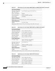
... hour 0.16 KVA 14 lb (6.4 kg) 1.73 x 16.1 x 17.5 in. (4.39 x 40.9 x 44.45 cm) Table A-10 Specifications for the Catalyst 3560G-48PS Switch Power Requirements AC input voltage 100 to 240 VAC (autoranging) 4 to 8 A, 50 to 60 Hz DC input voltages for RPS 675 +12 V...Dimensions (H x D x W) 1.73 x 16.1 x 17.5 in. (4.39 x 40.9 x 44.45 cm) Table A-11 Specifications for the Catalyst 3560V2-48PS and 3560V2-24PS Switch Environmental Ranges Operating temperature Storage temperature Relative humidity Operating altitude Storage altitude Power Requirements AC input voltage 32 to 113°F (0 to 45...
... hour 0.16 KVA 14 lb (6.4 kg) 1.73 x 16.1 x 17.5 in. (4.39 x 40.9 x 44.45 cm) Table A-10 Specifications for the Catalyst 3560G-48PS Switch Power Requirements AC input voltage 100 to 240 VAC (autoranging) 4 to 8 A, 50 to 60 Hz DC input voltages for RPS 675 +12 V...Dimensions (H x D x W) 1.73 x 16.1 x 17.5 in. (4.39 x 40.9 x 44.45 cm) Table A-11 Specifications for the Catalyst 3560V2-48PS and 3560V2-24PS Switch Environmental Ranges Operating temperature Storage temperature Relative humidity Operating altitude Storage altitude Power Requirements AC input voltage 32 to 113°F (0 to 45...
Hardware Installation Guide
Page 90
...Specifications Table A-11 Specifications for the Catalyst 3560V2-48PS and 3560V2-24PS Switch (continued) Environmental Ranges DC input voltages for RPS 2300 and 675 +12 V @14 A and -48 V @7.8 A Power consumption 560 W Power dissipation 220 W, 690 BTUs per hour Power rating 0.56 kVA Power over Ethernet Range from 4 to 15.4 W per port, up to 370 W switch....81 x 17.5 in. (4.4 x 30 x 44.45 cm) Table A-13 Specifications for the Catalyst 3560V2-24TS-SD Switch Environmental Ranges Operating temperature Storage temperature Relative humidity Operating altitude Storage altitude 32 to 113...
...Specifications Table A-11 Specifications for the Catalyst 3560V2-48PS and 3560V2-24PS Switch (continued) Environmental Ranges DC input voltages for RPS 2300 and 675 +12 V @14 A and -48 V @7.8 A Power consumption 560 W Power dissipation 220 W, 690 BTUs per hour Power rating 0.56 kVA Power over Ethernet Range from 4 to 15.4 W per port, up to 370 W switch....81 x 17.5 in. (4.4 x 30 x 44.45 cm) Table A-13 Specifications for the Catalyst 3560V2-24TS-SD Switch Environmental Ranges Operating temperature Storage temperature Relative humidity Operating altitude Storage altitude 32 to 113...