
Hardware Installation Guide
Page 3
... i-viii Obtaining Documentation and Submitting a Service Request i-ix Product Overview 1-1 Setting Up the Switch 1-1 Features 1-1 Front Panel Description 1-3 Fast Ethernet Switch Front Panel Descriptions 1-3 Gigabit Ethernet Switch Front Panel Descriptions 1-6 10/100 and 10/100/1000 Ports 1-8 PoE Ports 1-9 SFP ...Purpose Port LEDs 1-15 Cable Guard 1-15 Rear Panel Description 1-15 Internal Power Supply 1-18 DC Power Connector 1-18 Cisco RPS 1-19 Cisco RPS 2300 1-19 Cisco RPS 675 1-19 Console Port 1-19 Security Slots 1-20 Management Options 1-20 Catalyst 3560 Switch Hardware Installation Guide iii
... i-viii Obtaining Documentation and Submitting a Service Request i-ix Product Overview 1-1 Setting Up the Switch 1-1 Features 1-1 Front Panel Description 1-3 Fast Ethernet Switch Front Panel Descriptions 1-3 Gigabit Ethernet Switch Front Panel Descriptions 1-6 10/100 and 10/100/1000 Ports 1-8 PoE Ports 1-9 SFP ...Purpose Port LEDs 1-15 Cable Guard 1-15 Rear Panel Description 1-15 Internal Power Supply 1-18 DC Power Connector 1-18 Cisco RPS 1-19 Cisco RPS 2300 1-19 Cisco RPS 675 1-19 Console Port 1-19 Security Slots 1-20 Management Options 1-20 Catalyst 3560 Switch Hardware Installation Guide iii

Hardware Installation Guide
Page 4
... SFP Modules 2-21 Connecting to 1000BASE-T SFP Modules 2-22 Connecting to a Dual-Purpose Port 2-23 Where to the Switch for Installation 3-1 Warnings 3-2 Installation Guidelines 3-5 Equipment That You Supply 3-6 Catalyst 3560 Switch Hardware Installation Guide iv OL-6337-07 and 12-Port Switches) 3-1 Preparing for Wall Mounting 2-12 Attaching the RPS Connector Cover 2-13 Mounting the...
... SFP Modules 2-21 Connecting to 1000BASE-T SFP Modules 2-22 Connecting to a Dual-Purpose Port 2-23 Where to the Switch for Installation 3-1 Warnings 3-2 Installation Guidelines 3-5 Equipment That You Supply 3-6 Catalyst 3560 Switch Hardware Installation Guide iv OL-6337-07 and 12-Port Switches) 3-1 Preparing for Wall Mounting 2-12 Attaching the RPS Connector Cover 2-13 Mounting the...

Hardware Installation Guide
Page 11
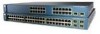
..., page 1-20 Setting Up the Switch See the Catalyst 3560 Switch Getting Started Guide for instructions on AC power and supplies backup DC power to the switches. The Catalyst 3560-8PC and the Catalyst 3560-12PC-S compact switches provide the same Power over Ethernet (PoE) connectivity and can connect devices like workstations, Cisco Wireless Access Points, Cisco IP Phones, and other network devices...
..., page 1-20 Setting Up the Switch See the Catalyst 3560 Switch Getting Started Guide for instructions on AC power and supplies backup DC power to the switches. The Catalyst 3560-8PC and the Catalyst 3560-12PC-S compact switches provide the same Power over Ethernet (PoE) connectivity and can connect devices like workstations, Cisco Wireless Access Points, Cisco IP Phones, and other network devices...
Hardware Installation Guide
Page 22
.... 1-12 Catalyst 3560 Switch Hardware Installation Guide OL-6337-07 The RPS is in standby mode or in a switch has failed, and the RPS is providing power to the switch (redundancy has been allocated to this device). Press the Standby/Active button on the RPS, and the LED should turn green. Contact Cisco. The internal power supply in...
.... 1-12 Catalyst 3560 Switch Hardware Installation Guide OL-6337-07 The RPS is in standby mode or in a switch has failed, and the RPS is providing power to the switch (redundancy has been allocated to this device). Press the Standby/Active button on the RPS, and the LED should turn green. Contact Cisco. The internal power supply in...
Hardware Installation Guide
Page 25
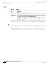
...SFP module is installed. Rear Panel Description • Internal Power Supply, page 1-18 • Cisco RPS, page 1-19 • Console Port, page 1-19 • Security Slots, page 1-20 Note The Catalyst 3560-8PC and the Catalyst 3560-12PC-S switches do not have the same meaning as an SFP module,...the cable guide (see Figure 1-13) show how the port is being accidentally removed. To order a cable guard (CBLGRD-C3560-12PC or CBLGRD-C3560-8PC), contact your Cisco representative. Chapter 1 Product Overview Rear Panel Description Dual-Purpose Port LEDs The LEDs on a dual-purpose port (see "...
...SFP module is installed. Rear Panel Description • Internal Power Supply, page 1-18 • Cisco RPS, page 1-19 • Console Port, page 1-19 • Security Slots, page 1-20 Note The Catalyst 3560-8PC and the Catalyst 3560-12PC-S switches do not have the same meaning as an SFP module,...the cable guide (see Figure 1-13) show how the port is being accidentally removed. To order a cable guard (CBLGRD-C3560-12PC or CBLGRD-C3560-8PC), contact your Cisco representative. Chapter 1 Product Overview Rear Panel Description Dual-Purpose Port LEDs The LEDs on a dual-purpose port (see "...
Hardware Installation Guide
Page 28
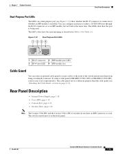
... 1 2 1 Heat sinks 2 AC power connector Internal Power Supply An internal power supply powers the switch. The internal power supply is not in this range, the switch might not operate properly or might be damaged. 1-18 Catalyst 3560 Switch Hardware Installation Guide OL-6337-07 Use the supplied AC power cord to connect the AC power connector to DC Power." DC Power Connector The Catalyst 3560V2-24TS-SD has...
... 1 2 1 Heat sinks 2 AC power connector Internal Power Supply An internal power supply powers the switch. The internal power supply is not in this range, the switch might not operate properly or might be damaged. 1-18 Catalyst 3560 Switch Hardware Installation Guide OL-6337-07 Use the supplied AC power cord to connect the AC power connector to DC Power." DC Power Connector The Catalyst 3560V2-24TS-SD has...

Hardware Installation Guide
Page 29
... RPS is connected to the Catalyst 3560V2-24TS-SD switch, the switch is 675 W. It automatically senses when the internal power supply of a connected switch fails and provides power to the failed switch, preventing loss of network traffic. The Cisco RPS 675 has two output levels: -48 V and 12 V. For complete information about the Cisco RPS products, including compatibility matrixes...
... RPS is connected to the Catalyst 3560V2-24TS-SD switch, the switch is 675 W. It automatically senses when the internal power supply of a connected switch fails and provides power to the failed switch, preventing loss of network traffic. The Cisco RPS 675 has two output levels: -48 V and 12 V. For complete information about the Cisco RPS products, including compatibility matrixes...

Hardware Installation Guide
Page 36
and 48-Port Switches) Warning This equipment must be connected through the use of a special tool, lock and key or other means of security. Statement 1024 Warning This unit might have more than one power supply connection. Statement 1040 Warning For connections outside the ...-energize the unit. Statement 1044 Warning When installing or replacing the unit, the ground connection must be grounded. Statement 1074 Catalyst 3560 Switch Hardware Installation Guide 2-4 OL-6337-07 You are made aware of this device. Avoid using uninsulated exposed metal contacts, conductors...
and 48-Port Switches) Warning This equipment must be connected through the use of a special tool, lock and key or other means of security. Statement 1024 Warning This unit might have more than one power supply connection. Statement 1040 Warning For connections outside the ...-energize the unit. Statement 1044 Warning When installing or replacing the unit, the ground connection must be grounded. Statement 1074 Catalyst 3560 Switch Hardware Installation Guide 2-4 OL-6337-07 You are made aware of this device. Avoid using uninsulated exposed metal contacts, conductors...

Hardware Installation Guide
Page 38
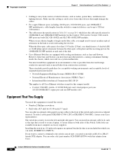
... provide guidelines for acceptable working environments and acceptable levels of the link. • Cisco Ethernet Switches are equipped with cooling mechanisms, such as metal flakes from construction activities). Catalyst 3560-8PC switch-8 10/100 PoE ports and 1 dual-purpose port (one 10/100/1000BASE-T ...the receiving port on Cisco.com describes the box contents. Tools and Equipment You need to supply a number-2 Phillips screwdriver to the switch, put the RPS in standby mode. To power on the switch, connect one SFP module slot) Box Contents The switch getting started guide on...
... provide guidelines for acceptable working environments and acceptable levels of the link. • Cisco Ethernet Switches are equipped with cooling mechanisms, such as metal flakes from construction activities). Catalyst 3560-8PC switch-8 10/100 PoE ports and 1 dual-purpose port (one 10/100/1000BASE-T ...the receiving port on Cisco.com describes the box contents. Tools and Equipment You need to supply a number-2 Phillips screwdriver to the switch, put the RPS in standby mode. To power on the switch, connect one SFP module slot) Box Contents The switch getting started guide on...
Hardware Installation Guide
Page 43
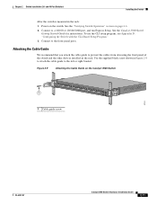
Connect to prevent the cables from obscuring the front panel of the switch and the other devices installed in the rack. Use the supplied black screw shown in the rack: 1. and 48-Port Switches) Installing the Switch After the switch is mounted in Figure 2-9 to attach the cable guide to a 10/... to the left or right bracket. To use the CLI setup program, see Appendix D, "Configuring the Switch with the CLI-Based Setup Program." 3. Chapter 2 Switch Installation (24- Power on the Catalyst 3560 Switch 1 SYST RPS STAT DUPLX SPEED PoE MODE 1 1X 2X 23 45 67 8 9 10 11 12 13 14 ...
Connect to prevent the cables from obscuring the front panel of the switch and the other devices installed in the rack. Use the supplied black screw shown in the rack: 1. and 48-Port Switches) Installing the Switch After the switch is mounted in Figure 2-9 to attach the cable guide to a 10/... to the left or right bracket. To use the CLI setup program, see Appendix D, "Configuring the Switch with the CLI-Based Setup Program." 3. Chapter 2 Switch Installation (24- Power on the Catalyst 3560 Switch 1 SYST RPS STAT DUPLX SPEED PoE MODE 1 1X 2X 23 45 67 8 9 10 11 12 13 14 ...
Hardware Installation Guide
Page 46
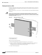
... could result in a hazardous situation to people and damage to a firmly attached plywood mounting backboard. Mount the switch with the front panel facing down. Power on page 2-6. 2. Connect to a 10/100 or 10/100/1000 port, and run Express Setup. and 48...1 User-supplied screws After the switch is attached securely to wall studs or to the system. Statement 378 Figure 2-12 Mounting the Switch on page 2-12 for instructions. Connect to the front-panel ports. 2-14 Catalyst 3560 Switch Hardware Installation Guide OL-6337-07 See the Catalyst 3560 Switch Getting Started...
... could result in a hazardous situation to people and damage to a firmly attached plywood mounting backboard. Mount the switch with the front panel facing down. Power on page 2-6. 2. Connect to a 10/100 or 10/100/1000 port, and run Express Setup. and 48...1 User-supplied screws After the switch is attached securely to wall studs or to the system. Statement 378 Figure 2-12 Mounting the Switch on page 2-12 for instructions. Connect to the front-panel ports. 2-14 Catalyst 3560 Switch Hardware Installation Guide OL-6337-07 See the Catalyst 3560 Switch Getting Started...

Hardware Installation Guide
Page 57
... Catalyst 3560-8PC and Catalyst 3560-12PC-S switches. and 48-Port Switches)." For installing the other Catalyst 3560 switches, see the "Connecting the Switch to Compatible Devices" section on page 2-20 Preparing for Installation, page 3-1 • Verifying Switch Operation, page 3-7 • Installing the Switch, page 3-7 • Where to Go Next, page 3-20 For information about connecting to interpret the power...
... Catalyst 3560-8PC and Catalyst 3560-12PC-S switches. and 48-Port Switches)." For installing the other Catalyst 3560 switches, see the "Connecting the Switch to Compatible Devices" section on page 2-20 Preparing for Installation, page 3-1 • Verifying Switch Operation, page 3-7 • Installing the Switch, page 3-7 • Where to Go Next, page 3-20 For information about connecting to interpret the power...
Hardware Installation Guide
Page 60
...1024 Warning This unit might have more than one power supply connection. Statement 1040 Warning For connections outside the building where the equipment is available. You are made aware of security. and 12-Port Switches) Warning This equipment must always be grounded. ...hazard. Statement 1046 Warning This warning symbol means danger. Statement 1071 Warning Voltages that accompanied this device. Statement 1074 Catalyst 3560 Switch Hardware Installation Guide 3-4 OL-6337-07 Never defeat the ground conductor or operate the equipment in a situation that suitable...
...1024 Warning This unit might have more than one power supply connection. Statement 1040 Warning For connections outside the building where the equipment is available. You are made aware of security. and 12-Port Switches) Warning This equipment must always be grounded. ...hazard. Statement 1046 Warning This warning symbol means danger. Statement 1071 Warning Voltages that accompanied this device. Statement 1074 Catalyst 3560 Switch Hardware Installation Guide 3-4 OL-6337-07 Never defeat the ground conductor or operate the equipment in a situation that suitable...
Hardware Installation Guide
Page 62
...you need to provide an RJ-45-to install the switch: • Number-2 Phillips screwdriver • Drill with that is away from most computer accessory suppliers. To order a cable guard (CBLGRD-C3560-12PC or CBLGRD-C3560-8PC), contact your Cisco representative. You can be up to 328 feet (...equipped with cooling mechanisms, such as radios, power lines, and fluorescent lighting fixtures. Catalyst 3560-8PC switch-8 10/100 PoE ports and 1 dual-purpose port (one 10/100/1000BASE-T copper port and one SFP module slot) Equipment That You Supply You need to insert an inline optical ...
...you need to provide an RJ-45-to install the switch: • Number-2 Phillips screwdriver • Drill with that is away from most computer accessory suppliers. To order a cable guard (CBLGRD-C3560-12PC or CBLGRD-C3560-8PC), contact your Cisco representative. You can be up to 328 feet (...equipped with cooling mechanisms, such as radios, power lines, and fluorescent lighting fixtures. Catalyst 3560-8PC switch-8 10/100 PoE ports and 1 dual-purpose port (one 10/100/1000BASE-T copper port and one SFP module slot) Equipment That You Supply You need to insert an inline optical ...
Hardware Installation Guide
Page 63
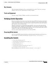
... If POST fails, the system LED remains amber. OL-6337-07 Catalyst 3560 Switch Hardware Installation Guide 3-7 To power on the switch, connect one end of the power cord to the AC power connector on and verify that the switch functions properly. If any item is missing or damaged, contact your...the POST, a series of tests that verifies that it on the switch, and connect the other end of the AC power cord to an AC power outlet. When the switch powers on page 3-7. Tools and Equipment You need to supply a number-2 Phillips screwdriver to run Express Setup. If POST completes ...
... If POST fails, the system LED remains amber. OL-6337-07 Catalyst 3560 Switch Hardware Installation Guide 3-7 To power on the switch, connect one end of the power cord to the AC power connector on and verify that the switch functions properly. If any item is missing or damaged, contact your...the POST, a series of tests that verifies that it on the switch, and connect the other end of the AC power cord to an AC power outlet. When the switch powers on page 3-7. Tools and Equipment You need to supply a number-2 Phillips screwdriver to run Express Setup. If POST completes ...

Hardware Installation Guide
Page 74
.... Power on page 3-19. 2. Figure 3-10 Mounting the Switch on a Wall 200916 12 1 Phillips flat-head screws 2 User-supplied screws After the switch is mounted on page 3-7. 3. and 12-Port Switches) Do not wall-mount the switch with the CLI-Based Setup Program." 4. Installing the Switch Chapter 3 Switch Installation (8- Connect to the front-panel ports. 3-18 Catalyst 3560 Switch Hardware...
.... Power on page 3-19. 2. Figure 3-10 Mounting the Switch on a Wall 200916 12 1 Phillips flat-head screws 2 User-supplied screws After the switch is mounted on page 3-7. 3. and 12-Port Switches) Do not wall-mount the switch with the CLI-Based Setup Program." 4. Installing the Switch Chapter 3 Switch Installation (8- Connect to the front-panel ports. 3-18 Catalyst 3560 Switch Hardware...

Hardware Installation Guide
Page 75
...-6337-07 Catalyst 3560 Switch Hardware Installation Guide 3-19 Step 1 Insert the power-cord retainer wire into one slot on the plastic holder. The retainer wire only fits into the slot on the bushing. Figure 3-13 Attach the Power-Cord Bushing ...Power Cord 250520 Step 4 Place the power cord bushing on the right side of the AC power cord connector, and insert the AC power cord (see Figure 3-14). and 12-Port Switches) Installing the Switch Securing the AC Power Cord The AC power-cord retainer is on the power cord with the supplied screw (see Figure 3-13). Chapter 3 Switch...
...-6337-07 Catalyst 3560 Switch Hardware Installation Guide 3-19 Step 1 Insert the power-cord retainer wire into one slot on the plastic holder. The retainer wire only fits into the slot on the bushing. Figure 3-13 Attach the Power-Cord Bushing ...Power Cord 250520 Step 4 Place the power cord bushing on the right side of the AC power cord connector, and insert the AC power cord (see Figure 3-14). and 12-Port Switches) Installing the Switch Securing the AC Power Cord The AC power-cord retainer is on the power cord with the supplied screw (see Figure 3-13). Chapter 3 Switch...
Hardware Installation Guide
Page 105
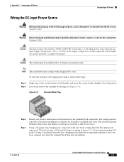
...supply voltage is removed from -36 to install, replace, or service this range, the switch might not operate properly or might be damaged. Statement 1003 Warning Only trained and qualified personnel should be installed with all applicable codes. Statement 1030 Caution You must connect the Catalyst 3560V2-24TS-SD switch only to a DC-input power... source that power is not in Figure C-6. The wiring sequence is positive to positive and ...
...supply voltage is removed from -36 to install, replace, or service this range, the switch might not operate properly or might be damaged. Statement 1003 Warning Only trained and qualified personnel should be installed with all applicable codes. Statement 1030 Caution You must connect the Catalyst 3560V2-24TS-SD switch only to a DC-input power... source that power is not in Figure C-6. The wiring sequence is positive to positive and ...
Hardware Installation Guide
Page 117
... switches 2-15 8- and 12-port switches 3-8, 3-12 mounting on a wall 8- and 12-port switches 3-8, 3-12 mounting on a shelf 24- and 48-port switches 2-12 8- and 12-port switches) 3-12 to 2-11 8- and 12-port switches 3-16 to 3-11 with a magnet (8- and 12-port switches 3-17 Catalyst 3560 Switch ... URL http //www.cisco.com/web/learning/index.html i-vii Mode button 1-11 mounting desk- and 12-port switches 3-17 OL-6337-07 site requirements 2-5, 3-5 starting the terminal emulation software D-2 See also procedures installing SFP modules 2-16 to 2-17 internal power supply 1-18 L LEDs ...
... switches 2-15 8- and 12-port switches 3-8, 3-12 mounting on a wall 8- and 12-port switches 3-8, 3-12 mounting on a shelf 24- and 48-port switches 2-12 8- and 12-port switches) 3-12 to 2-11 8- and 12-port switches 3-16 to 3-11 with a magnet (8- and 12-port switches 3-17 Catalyst 3560 Switch ... URL http //www.cisco.com/web/learning/index.html i-vii Mode button 1-11 mounting desk- and 12-port switches 3-17 OL-6337-07 site requirements 2-5, 3-5 starting the terminal emulation software D-2 See also procedures installing SFP modules 2-16 to 2-17 internal power supply 1-18 L LEDs ...
Hardware Installation Guide
Page 118
... four twisted-pair 1000BASE-T ports B-6 two twisted-pair B-5 PoE LED 1-13 shock hazard warning 2-4, 3-4 IN-4 Catalyst 3560 Switch Hardware Installation Guide port and interface troubleshooting 4-4 port LEDs 1-13 port modes changing 1-11 LEDs 1-13 See also Mode...D-3 running at power on 4-2 power connecting to 2-6, 3-7 connectors 1-19 power on 2-6, 3-7 Power over Ethernet See PoE power supply AC power outlet 1-18 internal 1-18 RPS connector 1-19 procedures connection 2-19 to 2-23 DC grounding C-2 to 3-18 publications, related i-viii R rack-mounting OL-6337-07 and 12-port switches) 3-7 to ...
... four twisted-pair 1000BASE-T ports B-6 two twisted-pair B-5 PoE LED 1-13 shock hazard warning 2-4, 3-4 IN-4 Catalyst 3560 Switch Hardware Installation Guide port and interface troubleshooting 4-4 port LEDs 1-13 port modes changing 1-11 LEDs 1-13 See also Mode...D-3 running at power on 4-2 power connecting to 2-6, 3-7 connectors 1-19 power on 2-6, 3-7 Power over Ethernet See PoE power supply AC power outlet 1-18 internal 1-18 RPS connector 1-19 procedures connection 2-19 to 2-23 DC grounding C-2 to 3-18 publications, related i-viii R rack-mounting OL-6337-07 and 12-port switches) 3-7 to ...

