
Hardware Installation Guide
Page 4
... Modules into SFP Module Slots 2-16 Removing SFP Modules from the Switch 2-8 Attaching Brackets to the Catalyst 3560 Switch 2-8 Mounting the Switch in a Rack 2-10 Attaching the Cable Guide 2-11 Wall-Mounting 2-12 Attaching the Brackets to Go Next 2-24 Switch Installation (8- and 12-Port Switches) 3-1 Preparing for Wall Mounting 2-12 Attaching the RPS Connector Cover 2-13...
... Modules into SFP Module Slots 2-16 Removing SFP Modules from the Switch 2-8 Attaching Brackets to the Catalyst 3560 Switch 2-8 Mounting the Switch in a Rack 2-10 Attaching the Cable Guide 2-11 Wall-Mounting 2-12 Attaching the Brackets to Go Next 2-24 Switch Installation (8- and 12-Port Switches) 3-1 Preparing for Wall Mounting 2-12 Attaching the RPS Connector Cover 2-13...

Hardware Installation Guide
Page 11
..., and troubleshooting help. Features The 24- See the switch software configuration guide for instructions on setting up your Catalyst switch. For power redundancy, all but the Catalyst 3560 8- Product Overview 1 C H A P T E R The Catalyst 3560 switch-also referred to as the switch-is an Ethernet switch to the switches. These topics are hot-swappable. OL-6337-07 Catalyst 3560 Switch Hardware Installation Guide 1-1 For...
..., and troubleshooting help. Features The 24- See the switch software configuration guide for instructions on setting up your Catalyst switch. For power redundancy, all but the Catalyst 3560 8- Product Overview 1 C H A P T E R The Catalyst 3560 switch-also referred to as the switch-is an Ethernet switch to the switches. These topics are hot-swappable. OL-6337-07 Catalyst 3560 Switch Hardware Installation Guide 1-1 For...

Hardware Installation Guide
Page 12
...=.) Switches running Cisco IOS Release 12.2(25)SEB or later support this patch cable. Catalyst 3560 Switch Hardware Installation Guide 1-2 OL-6337-07 and 12-port switches) • 1000BASE-BX10 • 1000BASE-LX • 1000BASE-SX • 1000BASE-T (only Catalyst 3560 24- ... or an RPS port. The Catalyst 3560-8PC and the Catalyst 3560-12PC-S switches are smaller than the other Catalyst 3560 switches. Features Chapter 1 Product Overview Table 1-1 Catalyst 3560 Switch Model Descriptions Switch Model Description FastEthernet Catalyst 3560-24PS 24 10/100 Power over Ethernet (...
...=.) Switches running Cisco IOS Release 12.2(25)SEB or later support this patch cable. Catalyst 3560 Switch Hardware Installation Guide 1-2 OL-6337-07 and 12-port switches) • 1000BASE-BX10 • 1000BASE-LX • 1000BASE-SX • 1000BASE-T (only Catalyst 3560 24- ... or an RPS port. The Catalyst 3560-8PC and the Catalyst 3560-12PC-S switches are smaller than the other Catalyst 3560 switches. Features Chapter 1 Product Overview Table 1-1 Catalyst 3560 Switch Model Descriptions Switch Model Description FastEthernet Catalyst 3560-24PS 24 10/100 Power over Ethernet (...

Hardware Installation Guide
Page 13
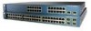
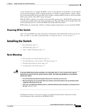
... grouped in Figure 1-1. Figure 1-1 Catalyst 3560-24PS and 3560V2-24PS Switch Front Panel OL-6337-07 97912 SYST RPS STAT DUPLX SPEED PoE MODE 12 1X 34 56 78 9 10 11 12 11X 2X 12X 13 14 13X 15 16 17 18 19 20 21 22 23 24 Catalyst 3560 SERIES PoE-24 23X 14X 24X 1 2 1 2 1 10.../100 PoE ports 2 SFP module slots Catalyst 3560 Switch...
... grouped in Figure 1-1. Figure 1-1 Catalyst 3560-24PS and 3560V2-24PS Switch Front Panel OL-6337-07 97912 SYST RPS STAT DUPLX SPEED PoE MODE 12 1X 34 56 78 9 10 11 12 11X 2X 12X 13 14 13X 15 16 17 18 19 20 21 22 23 24 Catalyst 3560 SERIES PoE-24 23X 14X 24X 1 2 1 2 1 10.../100 PoE ports 2 SFP module slots Catalyst 3560 Switch...

Hardware Installation Guide
Page 14
...-24TS-S, 3560V2-24TS, and 3560V2-24TS-SD Switch Front Panel 126808 SYST RPS STAT DUPLX SPEED MODE 12 1X 34 56 78 9 10 11 12 11X 2X 12X 13 14 13X 15 16 17 18 19 20 21 22 23 24 23X Catalyst 3560 SERIES 14X 24X 1 2 1 2 1 10/100 ports 2 SFP module slots... The 10/100 PoE ports on the switch are grouped in Figure 1-2. The SFP module slots are numbered 1 and 2. Port 3 is above port 4, and...
...-24TS-S, 3560V2-24TS, and 3560V2-24TS-SD Switch Front Panel 126808 SYST RPS STAT DUPLX SPEED MODE 12 1X 34 56 78 9 10 11 12 11X 2X 12X 13 14 13X 15 16 17 18 19 20 21 22 23 24 23X Catalyst 3560 SERIES 14X 24X 1 2 1 2 1 10/100 ports 2 SFP module slots... The 10/100 PoE ports on the switch are grouped in Figure 1-2. The SFP module slots are numbered 1 and 2. Port 3 is above port 4, and...

Hardware Installation Guide
Page 15
...the Catalyst 3560-8PC switch and the Catalyst 3560-12PC-S switch (Figure 1-5 and Figure 1-6). Figure 1-4 Catalyst 3560-48TS-S and 3560V2-48TS Switch Front Panel 126807 SYST RPS STAT DUPLX SPEED MODE 1 1X 2X 23 45 67 8 9 10 11 12 13 14 15 16 17 15X 17X 18 19 20 21 22 23 24 25... Panel SYST STAT DPLX SPD MODE CONSOLE 1x 2x 3x 4x 5x 6x 7x 8x Catalyst 2960 Series 1 157822 1 2 3 1 Console port 2 10/100 PoE ports 3 Dual-purpose port OL-6337-07 Catalyst 3560 Switch Hardware Installation Guide 1-5 The SFP module slots are on page 1-10. For more information on ...
...the Catalyst 3560-8PC switch and the Catalyst 3560-12PC-S switch (Figure 1-5 and Figure 1-6). Figure 1-4 Catalyst 3560-48TS-S and 3560V2-48TS Switch Front Panel 126807 SYST RPS STAT DUPLX SPEED MODE 1 1X 2X 23 45 67 8 9 10 11 12 13 14 15 16 17 15X 17X 18 19 20 21 22 23 24 25... Panel SYST STAT DPLX SPD MODE CONSOLE 1x 2x 3x 4x 5x 6x 7x 8x Catalyst 2960 Series 1 157822 1 2 3 1 Console port 2 10/100 PoE ports 3 Dual-purpose port OL-6337-07 Catalyst 3560 Switch Hardware Installation Guide 1-5 The SFP module slots are on page 1-10. For more information on ...

Hardware Installation Guide
Page 16
...24PS Switch Front Panel 119676 SYST RPS STAT DUPLX SPEED PoE MODE 12 1X 34 56 78 9 10 11 12 11X 2X 12X 13 14 13X 15 16 17 18 19 20 21 22 23 24 Catalyst 3560G SERIES PoE-24 23X 25 14X 27 24X 26 28 1 2 1 10/100/1000 ports 2 SFP module slots Catalyst... port Gigabit Ethernet Switch Front Panel Descriptions • Catalyst 3560G-24PS Switch Front Panel, Figure 1-7 on page 1-6 • Catalyst 3560G-24TS Switch Front Panel, Figure 1-8 on page 1-7 • Catalyst 3560G-48PS Switch Front Panel, Figure 1-9 on page 1-7 • Catalyst 3560G-48TS Switch Front Panel, Figure...
...24PS Switch Front Panel 119676 SYST RPS STAT DUPLX SPEED PoE MODE 12 1X 34 56 78 9 10 11 12 11X 2X 12X 13 14 13X 15 16 17 18 19 20 21 22 23 24 Catalyst 3560G SERIES PoE-24 23X 25 14X 27 24X 26 28 1 2 1 10/100/1000 ports 2 SFP module slots Catalyst... port Gigabit Ethernet Switch Front Panel Descriptions • Catalyst 3560G-24PS Switch Front Panel, Figure 1-7 on page 1-6 • Catalyst 3560G-24TS Switch Front Panel, Figure 1-8 on page 1-7 • Catalyst 3560G-48PS Switch Front Panel, Figure 1-9 on page 1-7 • Catalyst 3560G-48TS Switch Front Panel, Figure...

Hardware Installation Guide
Page 17
...on the left , as shown in Figure 1-8. Port 3 is above port 4, and so on. Figure 1-8 Catalyst 3560G-24TS Switch Front Panel 119677 SYST RPS STAT DUPLX SPEED MODE 12 1X 34 56 78 9 10 11 12 11X 2X... 12X 13 14 13X 15 16 17 18 19 20 21 22 23 24 23X Catalyst 3560G SERIES ...25 14X 27 24X 26 28 1 2 1 10/100/1000 ports 2 SFP module slots The 10/100/1000 PoE ports on the Catalyst 3560G-48PS switch are grouped in pairs. Port...
...on the left , as shown in Figure 1-8. Port 3 is above port 4, and so on. Figure 1-8 Catalyst 3560G-24TS Switch Front Panel 119677 SYST RPS STAT DUPLX SPEED MODE 12 1X 34 56 78 9 10 11 12 11X 2X... 12X 13 14 13X 15 16 17 18 19 20 21 22 23 24 23X Catalyst 3560G SERIES ...25 14X 27 24X 26 28 1 2 1 10/100/1000 ports 2 SFP module slots The 10/100/1000 PoE ports on the Catalyst 3560G-48PS switch are grouped in pairs. Port...

Hardware Installation Guide
Page 18
...-duplex transmission if the attached device supports it) and configures itself accordingly. You can set the 10/100/1000 ports to 52. Figure 1-10 Catalyst 3560G-48TS Switch Front Panel 119675 SYST RPS STAT DUPLX SPEED MODE 1 1X 2X 23 45 67 8 9 10 11 12 13 14 15 16 17 15X 17X... 18 19 20 21 22 23 24 25 26 27 28 29 30 31 32 16X 18X 33 31X 33X 34 35 36 37 38 39 40 41 42 43 44 45 46 47 48 47X 32X 34X Catalyst 3560G SERIES 49 51 48X 50 52 1 2 1 10/100...
...-duplex transmission if the attached device supports it) and configures itself accordingly. You can set the 10/100/1000 ports to 52. Figure 1-10 Catalyst 3560G-48TS Switch Front Panel 119675 SYST RPS STAT DUPLX SPEED MODE 1 1X 2X 23 45 67 8 9 10 11 12 13 14 15 16 17 15X 17X... 18 19 20 21 22 23 24 25 26 27 28 29 30 31 32 16X 18X 33 31X 33X 34 35 36 37 38 39 40 41 42 43 44 45 46 47 48 47X 32X 34X Catalyst 3560G SERIES 49 51 48X 50 52 1 2 1 10/100...

Hardware Installation Guide
Page 19
...3af-compliant powered device, a Cisco prestandard IP phone, or a Cisco prestandard Cisco access point, is a straight-through or crossover cable for redundant power. When you can use a crossover cable. On the Catalyst 3560-48PS, 3560G-48PS, and 3560V2-48PS switches, any 24 of the 48 10/100 ... for devices compliant with IEEE 802.3af and Cisco prestandard PoE support for Cisco IP Phones and Cisco Aironet Access Points. • Each of the Catalyst 3560-8PC, 3560-12PC-S, 3560-24PS, and 3560V2-24PS switch 10/100 ports or the Catalyst 3560G-24PS switch 10/100/1000 ports deliver up to use ...
...3af-compliant powered device, a Cisco prestandard IP phone, or a Cisco prestandard Cisco access point, is a straight-through or crossover cable for redundant power. When you can use a crossover cable. On the Catalyst 3560-48PS, 3560G-48PS, and 3560V2-48PS switches, any 24 of the 48 10/100 ... for devices compliant with IEEE 802.3af and Cisco prestandard PoE support for Cisco IP Phones and Cisco Aironet Access Points. • Each of the Catalyst 3560-8PC, 3560-12PC-S, 3560-24PS, and 3560V2-24PS switch 10/100 ports or the Catalyst 3560G-24PS switch 10/100/1000 ports deliver up to use ...
Hardware Installation Guide
Page 33
.../1000 Ports, page 2-19 • Connecting the Switch to Compatible Devices, page 2-20 • Where to Go Next, page 2-24 Preparing for installing, and connecting to the SFP modules apply to all Catalyst 3560 switches. The instructions in this chapter for connecting to interpret...the Catalyst 3560-8PC and Catalyst 3560 12-PC-S switches, see Chapter 3, "Switch Installation (8- and 48-Port Switches) This chapter describes how to the switch. and 12-Port Switches)." It also describes how to make connections to install the Catalyst 3560 24- and 48-port switches, including how to the switch ...
.../1000 Ports, page 2-19 • Connecting the Switch to Compatible Devices, page 2-20 • Where to Go Next, page 2-24 Preparing for installing, and connecting to the SFP modules apply to all Catalyst 3560 switches. The instructions in this chapter for connecting to interpret...the Catalyst 3560-8PC and Catalyst 3560 12-PC-S switches, see Chapter 3, "Switch Installation (8- and 48-Port Switches) This chapter describes how to the switch. and 12-Port Switches)." It also describes how to make connections to install the Catalyst 3560 24- and 48-port switches, including how to the switch ...
Hardware Installation Guide
Page 34
...and faceplates are translated into several languages in the Regulatory Compliance and Safety Information for Installation Chapter 2 Switch Installation (24- Statement 378 Catalyst 3560 Switch Hardware Installation Guide 2-2 OL-6337-07 Metal objects will heat up when connected to hazardous voltages and... currents inside the chassis; Statement 265 Warning Attach only the following Cisco RPS model to the switch, install an RPS ...
...and faceplates are translated into several languages in the Regulatory Compliance and Safety Information for Installation Chapter 2 Switch Installation (24- Statement 378 Catalyst 3560 Switch Hardware Installation Guide 2-2 OL-6337-07 Metal objects will heat up when connected to hazardous voltages and... currents inside the chassis; Statement 265 Warning Attach only the following Cisco RPS model to the switch, install an RPS ...

Hardware Installation Guide
Page 35
... is the only unit in the rack. • When mounting this unit in the rack. Statement 1022 OL-6337-07 Catalyst 3560 Switch Hardware Installation Guide 2-3 Ensure that the system remains stable. Statement 1017 Warning The plug-socket combination must take special precautions to... the power source. Statement 1006 Warning Class 1 laser product. Chapter 2 Switch Installation (24- Statement 1003 Warning Read the installation instructions before mounting or servicing the unit in a rack, you must be mounted at all...
... is the only unit in the rack. • When mounting this unit in the rack. Statement 1022 OL-6337-07 Catalyst 3560 Switch Hardware Installation Guide 2-3 Ensure that the system remains stable. Statement 1017 Warning The plug-socket combination must take special precautions to... the power source. Statement 1006 Warning Class 1 laser product. Chapter 2 Switch Installation (24- Statement 1003 Warning Read the installation instructions before mounting or servicing the unit in a rack, you must be mounted at all...

Hardware Installation Guide
Page 36
...1000 Ethernet. All connections must always be made aware of the hazards involved with electrical circuitry and be grounded. Statement 1074 Catalyst 3560 Switch Hardware Installation Guide 2-4 OL-6337-07 Statement 1040 Warning For connections outside the building where the equipment is available. Statement...that suitable grounding is installed, the following ports must be familiar with standard practices for Installation Chapter 2 Switch Installation (24- Preparing for preventing accidents. and 48-Port Switches) Warning This equipment must be aware of the hazard.
...1000 Ethernet. All connections must always be made aware of the hazards involved with electrical circuitry and be grounded. Statement 1074 Catalyst 3560 Switch Hardware Installation Guide 2-4 OL-6337-07 Statement 1040 Warning For connections outside the building where the equipment is available. Statement...that suitable grounding is installed, the following ports must be familiar with standard practices for Installation Chapter 2 Switch Installation (24- Preparing for preventing accidents. and 48-Port Switches) Warning This equipment must be aware of the hazard.

Hardware Installation Guide
Page 37
...multirack assembly, the temperature around the unit does not exceed 113°F (45°C). Access to avoid overloading the receiver. Catalyst 3560 switch SFP ports use shorter lengths of this product is installed in the link to ports is unrestricted. • Clearance to ...use both GLC-GE-100XX and GLC-FE-100XX SFP modules. Chapter 2 Switch Installation (24- OL-6337-07 Catalyst 3560 Switch Hardware Installation Guide 2-5 If the switch is DC-isolated (DC-I). and 48-Port Switches) Statement 371-Power Cable and AC Adapter Preparing for Installation Caution To comply ...
...multirack assembly, the temperature around the unit does not exceed 113°F (45°C). Access to avoid overloading the receiver. Catalyst 3560 switch SFP ports use shorter lengths of this product is installed in the link to ports is unrestricted. • Clearance to ...use both GLC-GE-100XX and GLC-FE-100XX SFP modules. Chapter 2 Switch Installation (24- OL-6337-07 Catalyst 3560 Switch Hardware Installation Guide 2-5 If the switch is DC-isolated (DC-I). and 48-Port Switches) Statement 371-Power Cable and AC Adapter Preparing for Installation Caution To comply ...

Hardware Installation Guide
Page 38
... matter: - Note When you should power the switch and verify that the switch passes POST. Statement 370 Catalyst 3560 Switch Hardware Installation Guide 2-6 OL-6337-07 National Electrical Manufacturers Association (NEMA) Type 1 - If your Cisco representative or reseller for the steps required to connect...and acceptable levels of the power cord to rack-mount the switch. Warning Attach only the following Cisco RPS model to run Express Setup. Verifying Switch Operation Chapter 2 Switch Installation (24- and 48-Port Switches) When the fiber-optic cable span is missing or damaged...
... matter: - Note When you should power the switch and verify that the switch passes POST. Statement 370 Catalyst 3560 Switch Hardware Installation Guide 2-6 OL-6337-07 National Electrical Manufacturers Association (NEMA) Type 1 - If your Cisco representative or reseller for the steps required to connect...and acceptable levels of the power cord to rack-mount the switch. Warning Attach only the following Cisco RPS model to run Express Setup. Verifying Switch Operation Chapter 2 Switch Installation (24- and 48-Port Switches) When the fiber-optic cable span is missing or damaged...
Hardware Installation Guide
Page 39
...Speed LEDs turn off and then reflect the switch operating status. The following guidelines are usually fatal. OL-6337-07 Catalyst 3560 Switch Hardware Installation Guide 2-7 LEDs can blink during the test. If a switch fails POST, the System LED turns amber. Call Cisco technical support representative if your safety: •...or servicing the unit in the rack. The System LED blinks green, and the other LEDs turn green. Chapter 2 Switch Installation (24- Powering Off the Switch After a successful POST, disconnect the power cord from the bottom to ensure that contains the...
...Speed LEDs turn off and then reflect the switch operating status. The following guidelines are usually fatal. OL-6337-07 Catalyst 3560 Switch Hardware Installation Guide 2-7 LEDs can blink during the test. If a switch fails POST, the System LED turns amber. Call Cisco technical support representative if your safety: •...or servicing the unit in the rack. The System LED blinks green, and the other LEDs turn green. Chapter 2 Switch Installation (24- Powering Off the Switch After a successful POST, disconnect the power cord from the bottom to ensure that contains the...

Hardware Installation Guide
Page 40
...23 45 67 8 9 10 11 12 13 14 15 16 15X 2X 16X 1 Phillips flat-head screws 97917 Catalyst 3560 Switch Hardware Installation Guide 2-8 OL-6337-07 Figure 2-2 1 Attaching Brackets for a 19-inch or a 24-inch rack. • For 19-inch racks, use bracket part number 700-8209-01 • For... 24-inch racks, use bracket part number 700-13248-01. Figure 2-2 through Figure 2-7 show how to attach each type bracket to the Catalyst 3560 Switch The bracket orientation and the brackets that you use depend on whether you install...
...23 45 67 8 9 10 11 12 13 14 15 16 15X 2X 16X 1 Phillips flat-head screws 97917 Catalyst 3560 Switch Hardware Installation Guide 2-8 OL-6337-07 Figure 2-2 1 Attaching Brackets for a 19-inch or a 24-inch rack. • For 19-inch racks, use bracket part number 700-8209-01 • For... 24-inch racks, use bracket part number 700-13248-01. Figure 2-2 through Figure 2-7 show how to attach each type bracket to the Catalyst 3560 Switch The bracket orientation and the brackets that you use depend on whether you install...
Hardware Installation Guide
Page 41
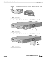
... Panel Forward 5.0A1-20R.05A-A2T,0IN500GV-6~0 HZ [email protected]@YMUO7A.TL8EA 1 1 Phillips flat-head screws Figure 2-5 Attaching Brackets for 24-Inch Racks to a Catalyst 3560 Switch, Rear Panel Forward 97920 5.0A1-20R.05A-A2T,0IN500GV-6~0 HZ [email protected]@YMUO7A.TL8EA 1 1 Phillips flat-head screws 97919 OL-6337-07...
... Panel Forward 5.0A1-20R.05A-A2T,0IN500GV-6~0 HZ [email protected]@YMUO7A.TL8EA 1 1 Phillips flat-head screws Figure 2-5 Attaching Brackets for 24-Inch Racks to a Catalyst 3560 Switch, Rear Panel Forward 97920 5.0A1-20R.05A-A2T,0IN500GV-6~0 HZ [email protected]@YMUO7A.TL8EA 1 1 Phillips flat-head screws 97919 OL-6337-07...
Hardware Installation Guide
Page 42
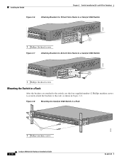
... Switch Chapter 2 Switch Installation (24- Figure 2-8 Mounting the Catalyst 3560 Switch in Figure 2-8. and 48-Port Switches) Figure 2-6 Attaching Brackets for 19-Inch Telco Racks to a Catalyst 3560 Switch 97921 40 41 42 43 44 45 46 47 48 47X Catalyst 3560 SERIES PoE-48 1 3 48X 2 4 1 1 Phillips flat-head screws Figure 2-7 Attaching Brackets for 24-Inch Telco Racks to a Catalyst 3560 Switch...
... Switch Chapter 2 Switch Installation (24- Figure 2-8 Mounting the Catalyst 3560 Switch in Figure 2-8. and 48-Port Switches) Figure 2-6 Attaching Brackets for 19-Inch Telco Racks to a Catalyst 3560 Switch 97921 40 41 42 43 44 45 46 47 48 47X Catalyst 3560 SERIES PoE-48 1 3 48X 2 4 1 1 Phillips flat-head screws Figure 2-7 Attaching Brackets for 24-Inch Telco Racks to a Catalyst 3560 Switch...

