
Hardware Installation Guide
Page 3
...1-6 Catalyst 2960G-24TC-L and Catalyst 2960G-48TC-L Switches 1-8 Catalyst 2960 8-Port Switches 1-9 Catalyst 2960PD-8TT-L Switch 1-9 Catalyst 2960-8TC-S, Catalyst 2960-8TC-L, and Catalyst 2960G-8TC -L Switches 1-10 10/100 Ports 1-11 10/100/1000 Ports 1-11 PoE Ports (Only Catalyst 2960 PoE Switches) 1-12 SFP ... 1-18 Cable Guard for the Catalyst 2960 8-Port Switches 1-19 Rear Panel Description 1-19 Internal Power Supply 1-20 Cisco RPS 1-20 Cisco RPS 2300 1-20 Cisco RPS 675 1-21 Console Port 1-21 Security Slots 1-21 Management Options 1-22 Network Configurations 1-22 Catalyst 2960 Switch Hardware...
...1-6 Catalyst 2960G-24TC-L and Catalyst 2960G-48TC-L Switches 1-8 Catalyst 2960 8-Port Switches 1-9 Catalyst 2960PD-8TT-L Switch 1-9 Catalyst 2960-8TC-S, Catalyst 2960-8TC-L, and Catalyst 2960G-8TC -L Switches 1-10 10/100 Ports 1-11 10/100/1000 Ports 1-11 PoE Ports (Only Catalyst 2960 PoE Switches) 1-12 SFP ... 1-18 Cable Guard for the Catalyst 2960 8-Port Switches 1-19 Rear Panel Description 1-19 Internal Power Supply 1-20 Cisco RPS 1-20 Cisco RPS 2300 1-20 Cisco RPS 675 1-21 Console Port 1-21 Security Slots 1-21 Management Options 1-22 Network Configurations 1-22 Catalyst 2960 Switch Hardware...
Hardware Installation Guide
Page 7
...configuration guide, the switch command reference, and the switch system message guide on the Cisco Training & Events web page: http://www.cisco.com/web/learning/index.html Purpose This guide describes the hardware features of data. If you are interested in this situation, you might do something ...that you are available on the Cisco.com Product Documentation home page. OL-7075-09 Catalyst 2960 Switch Hardware Installation Guide ...
...configuration guide, the switch command reference, and the switch system message guide on the Cisco Training & Events web page: http://www.cisco.com/web/learning/index.html Purpose This guide describes the hardware features of data. If you are interested in this situation, you might do something ...that you are available on the Cisco.com Product Documentation home page. OL-7075-09 Catalyst 2960 Switch Hardware Installation Guide ...

Hardware Installation Guide
Page 11
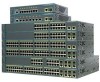
Table 1-1 Catalyst 2960 Switch Model Descriptions Switch Model Catalyst 2960-8TC-S Catalyst 2960-24-S Catalyst 2960-24TC-S Catalyst 2960-48TC-S Catalyst 2960-48TT-S Catalyst 2960-48PST-S Catalyst 2960-24PC-S Supported Software Image Description...Features You can deploy the 24- and 48-port Catalyst 2960 switches as in office workspaces and classrooms. See the switch software configuration guide for deployment examples. The Catalyst 2960 8-port compact switches provide the same Ethernet connectivity, but you can connect devices such as workstations, Cisco Wireless Access Points, Cisco...
Table 1-1 Catalyst 2960 Switch Model Descriptions Switch Model Catalyst 2960-8TC-S Catalyst 2960-24-S Catalyst 2960-24TC-S Catalyst 2960-48TC-S Catalyst 2960-48TT-S Catalyst 2960-48PST-S Catalyst 2960-24PC-S Supported Software Image Description...Features You can deploy the 24- and 48-port Catalyst 2960 switches as in office workspaces and classrooms. See the switch software configuration guide for deployment examples. The Catalyst 2960 8-port compact switches provide the same Ethernet connectivity, but you can connect devices such as workstations, Cisco Wireless Access Points, Cisco...

Hardware Installation Guide
Page 12
Features Chapter 1 Product Overview Table 1-1 Catalyst 2960 Switch Model Descriptions (continued) Switch Model Catalyst 2960-24LC-S Catalyst 2960-8TC-L Catalyst 2960G-8TC-L Catalyst 2960PD-8TT-L Catalyst 2960-24LT-L Catalyst 2960-24PC-L Catalyst 2960-24TC-L Catalyst 2960G-24TC-L Catalyst 2960-24TT-L ...for more information. These PoE switches comply with a magnet, have security lock slots, and do not have a fan. They can be mounted with Cisco prestandard PoE and IEEE 802.3af: • Catalyst 2960-24LC-S • Catalyst 2960-24LT-L • Catalyst 2960-24PC-L • Catalyst 2960...
Features Chapter 1 Product Overview Table 1-1 Catalyst 2960 Switch Model Descriptions (continued) Switch Model Catalyst 2960-24LC-S Catalyst 2960-8TC-L Catalyst 2960G-8TC-L Catalyst 2960PD-8TT-L Catalyst 2960-24LT-L Catalyst 2960-24PC-L Catalyst 2960-24TC-L Catalyst 2960G-24TC-L Catalyst 2960-24TT-L ...for more information. These PoE switches comply with a magnet, have security lock slots, and do not have a fan. They can be mounted with Cisco prestandard PoE and IEEE 802.3af: • Catalyst 2960-24LC-S • Catalyst 2960-24LT-L • Catalyst 2960-24PC-L • Catalyst 2960...

Hardware Installation Guide
Page 13
...information about switch support for an optional Cisco RPS 2300 or Cisco RPS 675 redundant power system that operates on specific switches, see the Cisco Gigabit Ethernet Transceiver Modules Compatibility Matrix at this Cisco.com URL: http://www.cisco.com/en/US/docs/interfaces_modules/transceiver_modules/...switches support all the SFP modules. The Catalyst 2960-8TC-S, Catalyst 2960-24TC-S, and Catalyst 2960-48TC-S switches support only 1000BASE-LX/LH, 1000BASE-SX, and 100BASE-FX SFP modules. Chapter 1 Product Overview Features These are supported on AC input and supplies backup DC...
...information about switch support for an optional Cisco RPS 2300 or Cisco RPS 675 redundant power system that operates on specific switches, see the Cisco Gigabit Ethernet Transceiver Modules Compatibility Matrix at this Cisco.com URL: http://www.cisco.com/en/US/docs/interfaces_modules/transceiver_modules/...switches support all the SFP modules. The Catalyst 2960-8TC-S, Catalyst 2960-24TC-S, and Catalyst 2960-48TC-S switches support only 1000BASE-LX/LH, 1000BASE-SX, and 100BASE-FX SFP modules. Chapter 1 Product Overview Features These are supported on AC input and supplies backup DC...

Hardware Installation Guide
Page 21
...mode. Pinouts for connections to autonegotiate, it ) and configures itself accordingly. When you connect the switch to enable the auto-MDIX feature. You can use a crossover cable. Therefore, you can also set these ports for the cables are described in Appendix B, "...speed and duplex autonegotiation. You can use a twisted four-pair, Category 5 or higher cable for connections to workstations, servers, routers, and Cisco IP Phones, be within 328 feet (100 meters). 100BASE-TX and 1000BASE-T traffic requires a Category 5 or higher cable. 10BASE-T traffic ...
...mode. Pinouts for connections to autonegotiate, it ) and configures itself accordingly. When you connect the switch to enable the auto-MDIX feature. You can use a crossover cable. Therefore, you can also set these ports for the cables are described in Appendix B, "...speed and duplex autonegotiation. You can use a twisted four-pair, Category 5 or higher cable for connections to workstations, servers, routers, and Cisco IP Phones, be within 328 feet (100 meters). 100BASE-TX and 1000BASE-T traffic requires a Category 5 or higher cable. 10BASE-T traffic ...
Hardware Installation Guide
Page 30
Cisco RPS Depending on the switch model, you can connect the switch to either of these RPS 2300 features through their internal power supply. The total maximum output power depends on page 1-13. Rear Panel Description Chapter 1 Product Overview Internal Power Supply... the supplied AC power cord to connect the AC power connector to one or two failed switches at a time. For complete information about the Cisco RPS products, including compatibility matrixes listing the supported RPS for each connected switch • Configure switch priority for each Catalyst 2960 switch, see "...
Cisco RPS Depending on the switch model, you can connect the switch to either of these RPS 2300 features through their internal power supply. The total maximum output power depends on page 1-13. Rear Panel Description Chapter 1 Product Overview Internal Power Supply... the supplied AC power cord to connect the AC power connector to one or two failed switches at a time. For complete information about the Cisco RPS products, including compatibility matrixes listing the supported RPS for each connected switch • Configure switch priority for each Catalyst 2960 switch, see "...
Hardware Installation Guide
Page 32
...." • CiscoView application The CiscoView device-management application displays the switch image that use the CLI, go /cna For information on Cisco IOS software and is enhanced to support desktop-switching features. For setup instructions that you purchase separately, can be downloaded from the CLI. Management Options Chapter 1 Product Overview Management Options...
...." • CiscoView application The CiscoView device-management application displays the switch image that use the CLI, go /cna For information on Cisco IOS software and is enhanced to support desktop-switching features. For setup instructions that you purchase separately, can be downloaded from the CLI. Management Options Chapter 1 Product Overview Management Options...

Hardware Installation Guide
Page 47
...list of the Catalyst 2960 switches. Chapter 2 Switch Installation (24- The auto-MDIX feature is amber while Spanning Tree Protocol (STP) discovers the topology and searches for this feature, see the switch software configuration guide or the switch command reference. Installing and Removing ... modules provide the uplink optical interfaces, laser send (TX) and laser receive (RX). Step 1 When connecting to workstations, servers, routers, and Cisco IP Phones, connect a straight-through 3 to 30 seconds, and then the port LED turns green. This can use a twisted four-pair, Category...
...list of the Catalyst 2960 switches. Chapter 2 Switch Installation (24- The auto-MDIX feature is amber while Spanning Tree Protocol (STP) discovers the topology and searches for this feature, see the switch software configuration guide or the switch command reference. Installing and Removing ... modules provide the uplink optical interfaces, laser send (TX) and laser receive (RX). Step 1 When connecting to workstations, servers, routers, and Cisco IP Phones, connect a straight-through 3 to 30 seconds, and then the port LED turns green. This can use a twisted four-pair, Category...
Hardware Installation Guide
Page 48
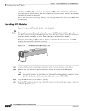
...the SFP module into place in front of the slot. Use only Cisco SFP modules on the module snap into the slot until you do not install or remove the SFP module with the Quality ID feature are supported. Removing and installing an SFP module can shorten its ... 2960 Switch Hardware Installation Guide OL-7075-09 Installing and Removing SFP Modules Chapter 2 Switch Installation (24- Cisco SFP modules and the Catalyst 2960 switch support the Quality ID feature. Disconnect all cables before removing or installing an SFP module. Installing SFP Modules Figure 2-14 shows an SFP...
...the SFP module into place in front of the slot. Use only Cisco SFP modules on the module snap into the slot until you do not install or remove the SFP module with the Quality ID feature are supported. Removing and installing an SFP module can shorten its ... 2960 Switch Hardware Installation Guide OL-7075-09 Installing and Removing SFP Modules Chapter 2 Switch Installation (24- Cisco SFP modules and the Catalyst 2960 switch support the Quality ID feature. Disconnect all cables before removing or installing an SFP module. Installing SFP Modules Figure 2-14 shows an SFP...
Hardware Installation Guide
Page 52
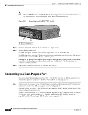
... the priority setting. For more information about 30 seconds, and then the port LED turns green. and 48-Port Switches) Note The auto-MDIX feature is off, the target device might not be turned on a target device. Figure 2-18 Connecting to SFP Modules" section on page 1-13. ...the network topology and searches for this port, see the switch software configuration guide or the switch command reference. For a detailed description of this feature, see the "Dual-Purpose Port" section on page 2-18. 2-20 Catalyst 2960 Switch Hardware Installation Guide OL-7075-09 Observe the port status ...
... the priority setting. For more information about 30 seconds, and then the port LED turns green. and 48-Port Switches) Note The auto-MDIX feature is off, the target device might not be turned on a target device. Figure 2-18 Connecting to SFP Modules" section on page 1-13. ...the network topology and searches for this port, see the switch software configuration guide or the switch command reference. For a detailed description of this feature, see the "Dual-Purpose Port" section on page 2-18. 2-20 Catalyst 2960 Switch Hardware Installation Guide OL-7075-09 Observe the port status ...

Hardware Installation Guide
Page 75
... interfaces privileged EXEC command to function at a marginal level. Verify that you have the correct cable for Cisco to be seated, but the other side does not have link. See the "Features" section on the connected device match and that they use Category 3 copper cable for a list of ... was used when a straight-through cable was required or the reverse. Disconnect and then reconnect the cable. Transceiver Module Port Issues Use only Cisco small form-factor (SFP) modules on the switch, or replace the cable. The cable might have encountered physical stress that causes it to ...
... interfaces privileged EXEC command to function at a marginal level. Verify that you have the correct cable for Cisco to be seated, but the other side does not have link. See the "Features" section on the connected device match and that they use Category 3 copper cable for a list of ... was used when a straight-through cable was required or the reverse. Disconnect and then reconnect the cable. Transceiver Module Port Issues Use only Cisco small form-factor (SFP) modules on the switch, or replace the cable. The cable might have encountered physical stress that causes it to ...
Hardware Installation Guide
Page 87
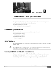
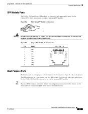
.../1000 Ports The 10/100/1000 Ethernet ports on the Catalyst 2960 switch use a two or four twisted-pair, straight-through cable wired for this feature, see the switch software configuration guide or the switch command reference. Connecting to 10BASE-T- OL-7075-09 Catalyst 2960 Switch Hardware Installation Guide B-1 B A P P... the ports to 10BASE-T- Figure B-5 shows the two twisted-pair, straight-through cable schematics. Note The auto-MDIX feature is enabled by default. Figure B-1 shows the pinout. Figure B-7 shows the four twisted-pair, straight-through cable schematics.
.../1000 Ports The 10/100/1000 Ethernet ports on the Catalyst 2960 switch use a two or four twisted-pair, straight-through cable wired for this feature, see the switch software configuration guide or the switch command reference. Connecting to 10BASE-T- OL-7075-09 Catalyst 2960 Switch Hardware Installation Guide B-1 B A P P... the ports to 10BASE-T- Figure B-5 shows the two twisted-pair, straight-through cable schematics. Note The auto-MDIX feature is enabled by default. Figure B-1 shows the pinout. Figure B-7 shows the four twisted-pair, straight-through cable schematics.
Hardware Installation Guide
Page 89
... disconnected fibers or connectors. Figure B-4 shows the pinouts. See the Catalyst 2960 switch release notes for this feature, see the switch software configuration guide or the switch command reference. Note The auto-MDIX feature is enabled by default. Do not stare into beams or view directly with optical instruments. See the Catalyst...
... disconnected fibers or connectors. Figure B-4 shows the pinouts. See the Catalyst 2960 switch release notes for this feature, see the switch software configuration guide or the switch command reference. Note The auto-MDIX feature is enabled by default. Do not stare into beams or view directly with optical instruments. See the Catalyst...
Hardware Installation Guide
Page 96
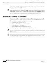
...page C-4 • Entering the Initial Configuration Information, page C-4 See the switch getting started guide for this release. Note The auto-MDIX feature is enabled by connecting the console port of what ships with the CLI-Based Setup Program After you enter the write memory command. Note You... information for a list of the switch to the serial port on the switch until you have entered the configuration information for this feature, see the switch software configuration guide or the switch command reference. Accessing the CLI Appendix C Configuring the Switch with your PC or...
...page C-4 • Entering the Initial Configuration Information, page C-4 See the switch getting started guide for this release. Note The auto-MDIX feature is enabled by connecting the console port of what ships with the CLI-Based Setup Program After you enter the write memory command. Note You... information for a list of the switch to the serial port on the switch until you have entered the configuration information for this feature, see the switch software configuration guide or the switch command reference. Accessing the CLI Appendix C Configuring the Switch with your PC or...
Hardware Installation Guide
Page 104
...port switches 2-2 8-port switches 3-2 Ethernet ports warning 3-3 examples, network configuration 1-1 Express Setup, accessing CLI by using C-1 F features 1-1 front panel 10/100/1000 ports 1-11 clearance 2-5, 3-4 description 1-4 to 1-17 dual-purpose ports 1-13 LEDs 1-14 to...4-4 duplex LED 1-16 E electrical noise, avoiding 2-5, 3-4 Ethernet and fiber-optic cable troubleshooting 4-3 Ethernet cable warning 24- Index Cisco IP Phones, connecting to 1-12, 2-15 Cisco RPS See RPS CiscoView 1-22 class 1 laser warning 2-3, 3-2 CLI accessing by using Express Setup C-1 accessing through console port ...
...port switches 2-2 8-port switches 3-2 Ethernet ports warning 3-3 examples, network configuration 1-1 Express Setup, accessing CLI by using C-1 F features 1-1 front panel 10/100/1000 ports 1-11 clearance 2-5, 3-4 description 1-4 to 1-17 dual-purpose ports 1-13 LEDs 1-14 to...4-4 duplex LED 1-16 E electrical noise, avoiding 2-5, 3-4 Ethernet and fiber-optic cable troubleshooting 4-3 Ethernet cable warning 24- Index Cisco IP Phones, connecting to 1-12, 2-15 Cisco RPS See RPS CiscoView 1-22 class 1 laser warning 2-3, 3-2 CLI accessing by using Express Setup C-1 accessing through console port ...

Software Guide
Page 3
... World Wide Web xix Documentation CD-ROM xix Ordering Documentation xix Documentation Feedback xix Obtaining Technical Assistance xx Cisco.com xx Technical Assistance Center xx Cisco TAC Web Site xxi Cisco TAC Escalation Center xxi Overview 1-1 Features 1-1 Management Options 1-6 Management Interface Options 1-6 Advantages of Using CMS and Clustering Switches 1-7 Network Configuration Examples 1-8 Design Concepts...
... World Wide Web xix Documentation CD-ROM xix Ordering Documentation xix Documentation Feedback xix Obtaining Technical Assistance xx Cisco.com xx Technical Assistance Center xx Cisco TAC Web Site xxi Cisco TAC Escalation Center xxi Overview 1-1 Features 1-1 Management Options 1-6 Management Interface Options 1-6 Advantages of Using CMS and Clustering Switches 1-7 Network Configuration Examples 1-8 Design Concepts...

Software Guide
Page 4
Contents 2 C H A P T E R Getting Started with CMS 2-1 Features 2-2 Front Panel View 2-4 Cluster Tree 2-5 Front-Panel Images 2-6 Redundant Power System LED 2-7 Port Modes and LEDs 2-8 VLAN Membership Modes 2-12 Topology View 2-13 Topology Icons 2-...
Contents 2 C H A P T E R Getting Started with CMS 2-1 Features 2-2 Front Panel View 2-4 Cluster Tree 2-5 Front-Panel Images 2-6 Redundant Power System LED 2-7 Port Modes and LEDs 2-8 VLAN Membership Modes 2-12 Topology View 2-13 Topology Icons 2-...

Software Guide
Page 6
... TACACS+ and RADIUS 5-17 Access Modes in CMS 5-17 Management VLAN 5-18 Network Port 5-19 NAT Commands 5-19 LRE Profiles 5-19 Availability of Switch-Specific Features in Switch Clusters 5-19 Creating a Switch Cluster 5-19 Enabling a Command Switch 5-20 Adding Member Switches 5-21 Creating a Cluster Standby Group 5-23 Verifying a Switch Cluster 5-25...
... TACACS+ and RADIUS 5-17 Access Modes in CMS 5-17 Management VLAN 5-18 Network Port 5-19 NAT Commands 5-19 LRE Profiles 5-19 Availability of Switch-Specific Features in Switch Clusters 5-19 Creating a Switch Cluster 5-19 Enabling a Command Switch 5-20 Adding Member Switches 5-21 Creating a Cluster Standby Group 5-23 Verifying a Switch Cluster 5-25...

Software Guide
Page 7
... Static Addresses 6-19 Removing Static Addresses 6-19 Configuring Static Addresses for EtherChannel Port Groups 6-20 Configuring CGMP 6-20 Enabling the Fast Leave Feature 6-21 Disabling the CGMP Fast Leave Feature 6-21 Changing the CGMP Router Hold-Time 6-22 Removing Multicast Groups 6-22 Configuring IGMP Filtering 6-23 Configuring IGMP Profiles 6-23 Applying IGMP...
... Static Addresses 6-19 Removing Static Addresses 6-19 Configuring Static Addresses for EtherChannel Port Groups 6-20 Configuring CGMP 6-20 Enabling the Fast Leave Feature 6-21 Disabling the CGMP Fast Leave Feature 6-21 Changing the CGMP Router Hold-Time 6-22 Removing Multicast Groups 6-22 Configuring IGMP Filtering 6-23 Configuring IGMP Profiles 6-23 Applying IGMP...