
Hardware Installation Guide
Page 1
Catalyst 2960 Switch Hardware Installation Guide March 2010 Americas Headquarters Cisco Systems, Inc. 170 West Tasman Drive San Jose, CA 95134-1706 USA http://www.cisco.com Tel: 408 526-4000 800 553-NETS (6387) Fax: 408 527-0883 Text Part Number: OL-7075-09
Catalyst 2960 Switch Hardware Installation Guide March 2010 Americas Headquarters Cisco Systems, Inc. 170 West Tasman Drive San Jose, CA 95134-1706 USA http://www.cisco.com Tel: 408 526-4000 800 553-NETS (6387) Fax: 408 527-0883 Text Part Number: OL-7075-09

Hardware Installation Guide
Page 2
... A PARTICULAR PURPOSE AND NONINFRINGEMENT OR ARISING FROM A COURSE OF DEALING, USAGE, OR TRADE PRACTICE. CCDE, CCENT, CCSI, Cisco Eos, Cisco Explorer, Cisco HealthPresence, Cisco IronPort, the Cisco logo, Cisco Nurse Connect, Cisco Pulse, Cisco SensorBase, Cisco StackPower, Cisco StadiumVision, Cisco TelePresence, Cisco TrustSec, Cisco Unified Computing System, Cisco WebEx, DCE, Flip Channels, Flip for FCC compliance of TCP header compression is , make certain the equipment...
... A PARTICULAR PURPOSE AND NONINFRINGEMENT OR ARISING FROM A COURSE OF DEALING, USAGE, OR TRADE PRACTICE. CCDE, CCENT, CCSI, Cisco Eos, Cisco Explorer, Cisco HealthPresence, Cisco IronPort, the Cisco logo, Cisco Nurse Connect, Cisco Pulse, Cisco SensorBase, Cisco StackPower, Cisco StadiumVision, Cisco TelePresence, Cisco TrustSec, Cisco Unified Computing System, Cisco WebEx, DCE, Flip Channels, Flip for FCC compliance of TCP header compression is , make certain the equipment...

Hardware Installation Guide
Page 3
...-L, 2960-24PC-S, 2960-24LC-S, 2960-24TC-L, 2960-48TC-L, 2960-24LT-L, 2960-24TT-L, 2960-48TT-L, 2960-48PST-L, and 2960-48PST-S Switches 1-6 Catalyst 2960G-24TC-L and Catalyst 2960G-48TC-L Switches 1-8 Catalyst 2960 8-Port Switches 1-9 Catalyst... Dual-Purpose Port 1-13 Power Input Port (Catalyst 2960PD-8TT-L Switch) 1-13 LEDs 1-14 System LED 1-15 RPS LED 1-16 Port LEDs and Modes 1-16 Dual-Purpose Port LEDs 1-18... 8-Port Switches 1-19 Rear Panel Description 1-19 Internal Power Supply 1-20 Cisco RPS 1-20 Cisco RPS 2300 1-20 Cisco RPS 675 1-21 Console Port 1-21 Security Slots 1-21 Management Options 1-...
...-L, 2960-24PC-S, 2960-24LC-S, 2960-24TC-L, 2960-48TC-L, 2960-24LT-L, 2960-24TT-L, 2960-48TT-L, 2960-48PST-L, and 2960-48PST-S Switches 1-6 Catalyst 2960G-24TC-L and Catalyst 2960G-48TC-L Switches 1-8 Catalyst 2960 8-Port Switches 1-9 Catalyst... Dual-Purpose Port 1-13 Power Input Port (Catalyst 2960PD-8TT-L Switch) 1-13 LEDs 1-14 System LED 1-15 RPS LED 1-16 Port LEDs and Modes 1-16 Dual-Purpose Port LEDs 1-18... 8-Port Switches 1-19 Rear Panel Description 1-19 Internal Power Supply 1-20 Cisco RPS 1-20 Cisco RPS 2300 1-20 Cisco RPS 675 1-21 Console Port 1-21 Security Slots 1-21 Management Options 1-...
Hardware Installation Guide
Page 7
...or 12.2 commands, see the switch software configuration guide, the switch command reference, and the switch system message guide on the Cisco Training & Events web page: http://www.cisco.com/web/learning/index.html Purpose This guide describes the hardware features of data. Preface Audience This...We assume that you are interested in this situation, you are available on the Cisco.com Product Documentation home page. Caution Means reader be careful. This guide does not describe system messages that you might receive or how to configure your switch. Conventions This document...
...or 12.2 commands, see the switch software configuration guide, the switch command reference, and the switch system message guide on the Cisco Training & Events web page: http://www.cisco.com/web/learning/index.html Purpose This guide describes the hardware features of data. Preface Audience This...We assume that you are interested in this situation, you are available on the Cisco.com Product Documentation home page. Caution Means reader be careful. This guide does not describe system messages that you might receive or how to configure your switch. Conventions This document...

Hardware Installation Guide
Page 8
...is for the Catalyst 2960 Switch guide. Related Documentation These documents provide complete information about related products, see these documents on Cisco.com: • Getting Started with standard practices for the latest information. • Catalyst 2960 Switch Software Configuration Guide •... • Catalyst 3750, 3560, 3550, 2970, and 2960 Switch System Message Guide • Device manager online help (available on the switch) • Cisco Network Assistant online help (available on Cisco.com for preventing accidents. The EMC regulatory statements are available from this...
...is for the Catalyst 2960 Switch guide. Related Documentation These documents provide complete information about related products, see these documents on Cisco.com: • Getting Started with standard practices for the latest information. • Catalyst 2960 Switch Software Configuration Guide •... • Catalyst 3750, 3560, 3550, 2970, and 2960 Switch System Message Guide • Device manager online help (available on the switch) • Cisco Network Assistant online help (available on Cisco.com for preventing accidents. The EMC regulatory statements are available from this...
Hardware Installation Guide
Page 9
... and set content to be delivered directly to your desktop using a reader application. OL-7075-09 Catalyst 2960 Switch Hardware Installation Guide ix Preface • Cisco Redundant Power System 2300 Hardware Installation Guide • Cisco RPS 675 Redundant Power System Hardware Installation Guide These compatibility matrix documents are a free service and...
... and set content to be delivered directly to your desktop using a reader application. OL-7075-09 Catalyst 2960 Switch Hardware Installation Guide ix Preface • Cisco Redundant Power System 2300 Hardware Installation Guide • Cisco RPS 675 Redundant Power System Hardware Installation Guide These compatibility matrix documents are a free service and...

Hardware Installation Guide
Page 13
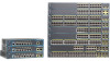
...Catalyst 2960-8TC-L, 2960G-8TC-L, and 2960-8TC-S switches do not have a redundant power system (RPS) connector for an optional Cisco RPS 2300 or Cisco RPS 675 redundant power system that operates on Cisco.com for the RPS models. Chapter 1 Product Overview Features These are supported on specific ... 100BASE-BX • 100BASE-FX • 100BASE-LX The Catalyst 2960-24PC-L, 2960-24PC-S, 2960-24LC-S, 2960-24TC-L, 2960-48TC-L, 2960-48PST-L, 2960-48PST-S, 2960G-24TC-L, and 2960G-48TC-L switches support all the SFP modules. These switches do not support the 1000BASE-T or GLC-GE-100FX SFP ...
...Catalyst 2960-8TC-L, 2960G-8TC-L, and 2960-8TC-S switches do not have a redundant power system (RPS) connector for an optional Cisco RPS 2300 or Cisco RPS 675 redundant power system that operates on Cisco.com for the RPS models. Chapter 1 Product Overview Features These are supported on specific ... 100BASE-BX • 100BASE-FX • 100BASE-LX The Catalyst 2960-24PC-L, 2960-24PC-S, 2960-24LC-S, 2960-24TC-L, 2960-48TC-L, 2960-48PST-L, 2960-48PST-S, 2960G-24TC-L, and 2960G-48TC-L switches support all the SFP modules. These switches do not support the 1000BASE-T or GLC-GE-100FX SFP ...

Hardware Installation Guide
Page 25
.... OL-7075-09 Catalyst 2960 Switch Hardware Installation Guide 1-15 Table 1-2 System LED Color Off Green Amber System Status System is only on . Chapter 1 Product Overview Figure 1-23 Catalyst 2960 Switch LEDs 8 Front Panel Description System LED 204612 1 2 3 4 5 6 SYST RPS STAT DUPLX SPEED ...1 SYST LED 5 Speed LED 2 RPS LED 6 PoE LED1 3 Status LED 7 Mode button 4 Duplex LED 8 Port LEDs 1. System is receiving power but is operating normally. System is not functioning properly. The System LED shows whether the system is receiving power and is functioning properly.
.... OL-7075-09 Catalyst 2960 Switch Hardware Installation Guide 1-15 Table 1-2 System LED Color Off Green Amber System Status System is only on . Chapter 1 Product Overview Figure 1-23 Catalyst 2960 Switch LEDs 8 Front Panel Description System LED 204612 1 2 3 4 5 6 SYST RPS STAT DUPLX SPEED ...1 SYST LED 5 Speed LED 2 RPS LED 6 PoE LED1 3 Status LED 7 Mode button 4 Duplex LED 8 Port LEDs 1. System is receiving power but is operating normally. System is not functioning properly. The System LED shows whether the system is receiving power and is functioning properly.

Hardware Installation Guide
Page 26
...has been allocated to this device). Table 1-3 RPS LED Color Off Green Blinking green Amber Blinking amber RPS Status RPS is the default mode. Contact Cisco Systems. The internal power supply in a switch has failed, and the RPS is in standby mode or in half-duplex mode. 2. For more information... about the individual ports (Table 1-4): Table 1-4 Modes for that power system. The PoE status. 1. RPS is only on the RPS, and the LED should turn green. The RPS is providing power to the switch (redundancy ...
...has been allocated to this device). Table 1-3 RPS LED Color Off Green Blinking green Amber Blinking amber RPS Status RPS is the default mode. Contact Cisco Systems. The internal power supply in a switch has failed, and the RPS is in standby mode or in half-duplex mode. 2. For more information... about the individual ports (Table 1-4): Table 1-4 Modes for that power system. The PoE status. 1. RPS is only on the RPS, and the LED should turn green. The RPS is providing power to the switch (redundancy ...
Hardware Installation Guide
Page 30
...on the installed power-supply modules. Cisco RPS Depending on the switch model, you can configure these Cisco redundant power systems (RPS) to provide backup power if the switch power supply fails: • "Cisco RPS 2300" section on page 1-20 • "Cisco RPS 675" section on page 1-... 2960PD-8TT-L switch does not have an RPS connector: Catalyst 8-port switches, 2960-24-S, 2960-24TC-S, 2960-48TC-S, 2960-48TT-S, 2960-48PST-S, 2960-24PC-S, and 2960-24LC-S switches. Rear Panel Description Chapter 1 Product Overview Internal Power Supply All switches other than the Catalyst 2960PD-...
...on the installed power-supply modules. Cisco RPS Depending on the switch model, you can configure these Cisco redundant power systems (RPS) to provide backup power if the switch power supply fails: • "Cisco RPS 2300" section on page 1-20 • "Cisco RPS 675" section on page 1-... 2960PD-8TT-L switch does not have an RPS connector: Catalyst 8-port switches, 2960-24-S, 2960-24TC-S, 2960-48TC-S, 2960-48TT-S, 2960-48PST-S, 2960-24PC-S, and 2960-24LC-S switches. Rear Panel Description Chapter 1 Product Overview Internal Power Supply All switches other than the Catalyst 2960PD-...

Hardware Installation Guide
Page 31
...; Obtain status reports for the RPS power-supply module • Read and monitor backup, failure, and exception history Cisco RPS 675 The Cisco 675 RPS is a redundant power system that supports six network devices and provides power to -DB-25 female DTE adapter. Security Slots The Catalyst 2960 8-port... "Connector and Cable Specifications" section on the left -side panel. You can install an optional cable lock, such as the type that adapter from Cisco. Console Port You can order a kit (part number ACS-DSBUASYN=) containing that is used to secure a laptop computer, to -DB-9 female cable...
...; Obtain status reports for the RPS power-supply module • Read and monitor backup, failure, and exception history Cisco RPS 675 The Cisco 675 RPS is a redundant power system that supports six network devices and provides power to -DB-25 female DTE adapter. Security Slots The Catalyst 2960 8-port... "Connector and Cable Specifications" section on the left -side panel. You can install an optional cable lock, such as the type that adapter from Cisco. Console Port You can order a kit (part number ACS-DSBUASYN=) containing that is used to secure a laptop computer, to -DB-9 female cable...
Hardware Installation Guide
Page 34
...metal object to the switch, install an RPS connector cover on the system or connect or disconnect cables during periods of clearance around the ventilation openings. Statement 265 Warning Attach only the following Cisco RPS model to power and ground and can cause severe bodily injury and... equipment damage. Failure to use the correct hardware or to power lines, remove jewelry (including rings, necklaces, and watches). Statement 171 Warning If a redundant power system (RPS) is ...
...metal object to the switch, install an RPS connector cover on the system or connect or disconnect cables during periods of clearance around the ventilation openings. Statement 265 Warning Attach only the following Cisco RPS model to power and ground and can cause severe bodily injury and... equipment damage. Failure to use the correct hardware or to power lines, remove jewelry (including rings, necklaces, and watches). Statement 171 Warning If a redundant power system (RPS) is ...
Hardware Installation Guide
Page 35
... trained and qualified personnel should be grounded. Warning For connections outside the building where the equipment is installed, the following guidelines are uncertain that the system remains stable. Statement 1006 Warning Class 1 laser product. Statement 1040. Statement 1044 OL-7075-09 Catalyst 2960 Switch Hardware Installation Guide 2-3 Statement 1024 Warning This...
... trained and qualified personnel should be grounded. Warning For connections outside the building where the equipment is installed, the following guidelines are uncertain that the system remains stable. Statement 1006 Warning Class 1 laser product. Statement 1040. Statement 1044 OL-7075-09 Catalyst 2960 Switch Hardware Installation Guide 2-3 Statement 1024 Warning This...

Hardware Installation Guide
Page 36
...2960 8-port switches. When you determine where to place the switch, be made aware of suspended particulate matter: • Network Equipment Building Systems (NEBS) GR-63-CORE • National Electrical Manufacturers Association (NEMA) Type 1 • International Electrotechnical Commission (IEC) IP-20 This...exist on page B-5, which can be no longer than 328 feet (100 meters). • The cables meet the specifications in a system malfunction. Statement 1072 Warning No user-serviceable parts inside the chassis, which lists the cable specifications for 1000BASE-X and 100BASE-X SFP ...
...2960 8-port switches. When you determine where to place the switch, be made aware of suspended particulate matter: • Network Equipment Building Systems (NEBS) GR-63-CORE • National Electrical Manufacturers Association (NEMA) Type 1 • International Electrotechnical Commission (IEC) IP-20 This...exist on page B-5, which can be no longer than 328 feet (100 meters). • The cables meet the specifications in a system malfunction. Statement 1072 Warning No user-serviceable parts inside the chassis, which lists the cable specifications for 1000BASE-X and 100BASE-X SFP ...

Hardware Installation Guide
Page 38
..., page 2-11 • Table- Statement 1006 Catalyst 2960 Switch Hardware Installation Guide 2-6 OL-7075-09 The System LED blinks green, and the other LEDs turn green. The following Cisco RPS model to all 24- Installing the Switch Chapter 2 Switch Installation (24- When the switch begins POST,... the System, RPS, Status, Duplex, and Speed LEDs turn off and then reflect the switch operating...
..., page 2-11 • Table- Statement 1006 Catalyst 2960 Switch Hardware Installation Guide 2-6 OL-7075-09 The System LED blinks green, and the other LEDs turn green. The following Cisco RPS model to all 24- Installing the Switch Chapter 2 Switch Installation (24- When the switch begins POST,... the System, RPS, Status, Duplex, and Speed LEDs turn off and then reflect the switch operating...
Hardware Installation Guide
Page 45
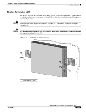
Chapter 2 Switch Installation (24- Statement 266 Warning If a redundant power system (RPS) is not connected to a firmly attached plywood mounting backboard. Statement 265 Figure 2-12 Mounting the Switch on a wall with the front panel facing up . ...
Chapter 2 Switch Installation (24- Statement 266 Warning If a redundant power system (RPS) is not connected to a firmly attached plywood mounting backboard. Statement 265 Figure 2-12 Mounting the Switch on a wall with the front panel facing up . ...

Hardware Installation Guide
Page 56
...Statement 1006 Warning Class 1 laser product. Preparing for Installation Chapter 3 Switch Installation (8-Port Switches) Warning Before working on equipment that the system remains stable. Statement 1004 Warning To prevent bodily injury when mounting or servicing this unit in a partially filled rack, load the rack... from the bottom to the top with stabilizing devices, install the stabilizers before connecting the system to the Catalyst 2960PD-8TT-L switch: Warning This product must be mounted at all times, because it serves as the main ...
...Statement 1006 Warning Class 1 laser product. Preparing for Installation Chapter 3 Switch Installation (8-Port Switches) Warning Before working on equipment that the system remains stable. Statement 1004 Warning To prevent bodily injury when mounting or servicing this unit in a partially filled rack, load the rack... from the bottom to the top with stabilizing devices, install the stabilizers before connecting the system to the Catalyst 2960PD-8TT-L switch: Warning This product must be mounted at all times, because it serves as the main ...

Hardware Installation Guide
Page 59
...power cord to the AC power connector on Cisco.com describes the box contents. When the POST completes successfully, the System LED remains green. After a successful POST, disconnect the power cord from Cisco. For information applicable to rack-mount the switch...Switch)" section on page 3-5. POST lasts approximately 1 minute. The System LED blinks green, and the other Catalyst 2960 switches, see Chapter 2, "Switch Installation (24- Call Cisco technical support representative if your Cisco representative or reseller for more information. or Shelf-Mounting (without ...
...power cord to the AC power connector on Cisco.com describes the box contents. When the POST completes successfully, the System LED remains green. After a successful POST, disconnect the power cord from Cisco. For information applicable to rack-mount the switch...Switch)" section on page 3-5. POST lasts approximately 1 minute. The System LED blinks green, and the other Catalyst 2960 switches, see Chapter 2, "Switch Installation (24- Call Cisco technical support representative if your Cisco representative or reseller for more information. or Shelf-Mounting (without ...
Hardware Installation Guide
Page 65
... the switch with its front panel facing up or sideways. OL-7075-09 Catalyst 2960 Switch Hardware Installation Guide 3-11 For information applicable to the system. Statement 378 Note Do not wall-mount the switch with its front panel facing down (as shown in a hazardous situation to people and damage to...
... the switch with its front panel facing up or sideways. OL-7075-09 Catalyst 2960 Switch Hardware Installation Guide 3-11 For information applicable to the system. Statement 378 Note Do not wall-mount the switch with its front panel facing down (as shown in a hazardous situation to people and damage to...

Hardware Installation Guide
Page 69
... Catalyst 2960 8-port switches in a 19-inch rack requires an optional bracket kit that the system remains stable. Warning To prevent bodily injury when mounting or servicing this unit in a partially filled rack, load the rack from Cisco. For information applicable to the opposite side. You can order a kit containing the 19...
... Catalyst 2960 8-port switches in a 19-inch rack requires an optional bracket kit that the system remains stable. Warning To prevent bodily injury when mounting or servicing this unit in a partially filled rack, load the rack from Cisco. For information applicable to the opposite side. You can order a kit containing the 19...