
Hardware Installation Guide
Page 8
... 2-9 RPS LED 2-9 Master LED 2-10 Port LEDs and Modes 2-10 Rear Panel Description 2-14 StackWise Ports 2-15 Power Connectors 2-16 Internal Power Supply Connector 2-16 Cisco RPS Connector 2-16 Console Port 2-17 Management Options 2-18 Network Configurations 2-19 Switch Installation 3-1 Preparing for Installation 3-1 Warnings 3-2 EMC Regulatory Statements 3-4 Catalyst 3750 Switch Hardware Installation Guide vi 78-15136-02
... 2-9 RPS LED 2-9 Master LED 2-10 Port LEDs and Modes 2-10 Rear Panel Description 2-14 StackWise Ports 2-15 Power Connectors 2-16 Internal Power Supply Connector 2-16 Cisco RPS Connector 2-16 Console Port 2-17 Management Options 2-18 Network Configurations 2-19 Switch Installation 3-1 Preparing for Installation 3-1 Warnings 3-2 EMC Regulatory Statements 3-4 Catalyst 3750 Switch Hardware Installation Guide vi 78-15136-02

Hardware Installation Guide
Page 12
Contents E A P P E N D I X INDEX Translated Safety Warnings E-1 Attaching the Cisco RPS (model PWR300-AC-RPS-N1) E-1 Attaching the Cisco RPS (model PWR675-AC-RPS-N1) E-2 Installation Warning E-4 Installation Instructions E-5 Jewelry Removal Warning E-6 Stacking the Chassis ...Warning E-17 Chassis Warning for Rack-Mounting and Servicing E-19 Redundant Power Supply Connection Warning E-24 Switch Installation Warning E-25 Restricted Area E-27 Ethernet Cable Shielding in Offices E-28 Laser Beam Exposure E-30 Laser Radiation E-31 E-32 Catalyst 3750 Switch Hardware Installation Guide x 78-15136-02
Contents E A P P E N D I X INDEX Translated Safety Warnings E-1 Attaching the Cisco RPS (model PWR300-AC-RPS-N1) E-1 Attaching the Cisco RPS (model PWR675-AC-RPS-N1) E-2 Installation Warning E-4 Installation Instructions E-5 Jewelry Removal Warning E-6 Stacking the Chassis ...Warning E-17 Chassis Warning for Rack-Mounting and Servicing E-19 Redundant Power Supply Connection Warning E-24 Switch Installation Warning E-25 Restricted Area E-27 Ethernet Cable Shielding in Offices E-28 Laser Beam Exposure E-30 Laser Radiation E-31 E-32 Catalyst 3750 Switch Hardware Installation Guide x 78-15136-02

Hardware Installation Guide
Page 14
...its service center will use the product, provided that the fan and power supply warranty is limited to five (5) years from the announcement of the discontinuance. You can vary, depending on the customer location. c. d. Cisco reserves the right to view the document. Click Go. In the... Authorization (RMA) request. To read translated and localized warranty information about your product, follow these steps: a. The Cisco warranty page appears. Catalyst 3750 Switch Hardware Installation Guide xii 78-15136-02 Select the language in the Warranty Document Number field: 78-6310-02C0...
...its service center will use the product, provided that the fan and power supply warranty is limited to five (5) years from the announcement of the discontinuance. You can vary, depending on the customer location. c. d. Cisco reserves the right to view the document. Click Go. In the... Authorization (RMA) request. To read translated and localized warranty information about your product, follow these steps: a. The Cisco warranty page appears. Catalyst 3750 Switch Hardware Installation Guide xii 78-15136-02 Select the language in the Warranty Document Number field: 78-6310-02C0...

Hardware Installation Guide
Page 42
...Catalyst 3750-48TS-48 10/100 Ethernet ports and 4 SFP module slots - Connection for optional Cisco RPS 300 redundant power system that operates on AC input and supplies backup DC power output to nine switches in a stack by cabling the StackWise ports. Catalyst 3750 Switch Hardware Installation Guide 2-2 78-15136-02 StackWise ports are not user-configurable. • Switches...slots - You can either operate at 10 or 100 Mbps. • Configuration - Catalyst 3750G-12S-12 SFP module slots • The switches support these SFP modules: - 1000BASE-SX - 1000BASE-LX - 1000BASE-T Note When ...
...Catalyst 3750-48TS-48 10/100 Ethernet ports and 4 SFP module slots - Connection for optional Cisco RPS 300 redundant power system that operates on AC input and supplies backup DC power output to nine switches in a stack by cabling the StackWise ports. Catalyst 3750 Switch Hardware Installation Guide 2-2 78-15136-02 StackWise ports are not user-configurable. • Switches...slots - You can either operate at 10 or 100 Mbps. • Configuration - Catalyst 3750G-12S-12 SFP module slots • The switches support these SFP modules: - 1000BASE-SX - 1000BASE-LX - 1000BASE-T Note When ...

Hardware Installation Guide
Page 43
...(right). Port 3 is above port 4, and so on AC input and supplies backup DC power output to 28. 78-15136-02 Catalyst 3750 Switch Hardware Installation Guide 2-3 Front Panel Description The Catalyst 3750-24TS 10/100 ports are numbered 1 (left , as shown in... pairs. The SFP port numbers are numbered 1 through 24. Connection for optional Cisco RPS 675 redundant power system that operates on . Chapter 2 Product Overview Front Panel Description Note The Cisco RPS 300 does not support the Catalyst 3750G-24TS switch...
...(right). Port 3 is above port 4, and so on AC input and supplies backup DC power output to 28. 78-15136-02 Catalyst 3750 Switch Hardware Installation Guide 2-3 Front Panel Description The Catalyst 3750-24TS 10/100 ports are numbered 1 (left , as shown in... pairs. The SFP port numbers are numbered 1 through 24. Connection for optional Cisco RPS 675 redundant power system that operates on . Chapter 2 Product Overview Front Panel Description Note The Cisco RPS 300 does not support the Catalyst 3750G-24TS switch...

Hardware Installation Guide
Page 49
.... Table 2-1 System LED Color Off Green Amber System Status System is providing power to the switch (redundancy has been allocated to this device). 78-15136-02 Catalyst 3750 Switch Hardware Installation Guide 2-9 Contact Cisco Systems. The internal power supply in a fault condition. Chapter 2 Product Overview Front Panel Description System LED The System LED shows whether the system...
.... Table 2-1 System LED Color Off Green Amber System Status System is providing power to the switch (redundancy has been allocated to this device). 78-15136-02 Catalyst 3750 Switch Hardware Installation Guide 2-9 Contact Cisco Systems. The internal power supply in a fault condition. Chapter 2 Product Overview Front Panel Description System LED The System LED shows whether the system...

Hardware Installation Guide
Page 56
... supports input voltages between 100 and 240 VAC. Internal Power Supply Connector The internal power supply is powered through the internal power supply. Cisco RPS Connector Specific Cisco RPS modes support specific Catalyst 3750 switches: • Cisco RPS 300 (model PWR300-AC-RPS-N1) supports the Catalyst 3750-24TS, 3750G-24T, 3750G-12S, and 3750-48TS switches. • Cisco RPS 675 (model PWR675-AC-RPS-N1=) supports the...
... supports input voltages between 100 and 240 VAC. Internal Power Supply Connector The internal power supply is powered through the internal power supply. Cisco RPS Connector Specific Cisco RPS modes support specific Catalyst 3750 switches: • Cisco RPS 300 (model PWR300-AC-RPS-N1) supports the Catalyst 3750-24TS, 3750G-24T, 3750G-12S, and 3750-48TS switches. • Cisco RPS 675 (model PWR675-AC-RPS-N1=) supports the...

Hardware Installation Guide
Page 57
...information on the Cisco RPS 300, refer to the Cisco RPS 300 Redundant Power System Hardware Installation Guide. You can order a kit (part number ACS-DSBUASYN=) containing that adapter from Cisco. It automatically senses when the internal power supply of a connected device fails and provides power to the ...the Cisco RPS 675, refer to the Cisco RPS 675 Redundant Power System Hardware Installation Guide. If you want to connect the switch console port to a terminal, you need to provide an RJ-45-to the switch. For more information on page B-1. 78-15136-02 Catalyst 3750 Switch Hardware...
...information on the Cisco RPS 300, refer to the Cisco RPS 300 Redundant Power System Hardware Installation Guide. You can order a kit (part number ACS-DSBUASYN=) containing that adapter from Cisco. It automatically senses when the internal power supply of a connected device fails and provides power to the ...the Cisco RPS 675, refer to the Cisco RPS 675 Redundant Power System Hardware Installation Guide. If you want to connect the switch console port to a terminal, you need to provide an RJ-45-to the switch. For more information on page B-1. 78-15136-02 Catalyst 3750 Switch Hardware...

Hardware Installation Guide
Page 68
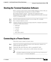
...need to provide a RJ-45-to a terminal, you should power the switch and verify that adapter from Cisco. StackWise cable: 0.5-meter, 1-meter, or 3-meter cable. Catalyst 3750 Switch Hardware Installation Guide 3-8 78-15136-02 Six Phillips flat-head ...power on the switch and observe POST: • Connecting a PC or Terminal to the Console Port, page 3-8 • Powering On the Switch and Running POST, page 3-10 Connecting a PC or Terminal to the Console Port To connect a PC to the console port, use the supplied RJ-45-to the switch (Catalyst 3750-24TS, 3750G-24T, and 3750-48TS switches...
...need to provide a RJ-45-to a terminal, you should power the switch and verify that adapter from Cisco. StackWise cable: 0.5-meter, 1-meter, or 3-meter cable. Catalyst 3750 Switch Hardware Installation Guide 3-8 78-15136-02 Six Phillips flat-head ...power on the switch and observe POST: • Connecting a PC or Terminal to the Console Port, page 3-8 • Powering On the Switch and Running POST, page 3-10 Connecting a PC or Terminal to the Console Port To connect a PC to the console port, use the supplied RJ-45-to the switch (Catalyst 3750-24TS, 3750G-24T, and 3750-48TS switches...

Hardware Installation Guide
Page 72
...; For concepts and procedures to manage switch stacks, refer to stack the switches. The Catalyst 3750-24TS, 3750G-24TS, and 3750-48TS switches are the same depth, and the Catalyst 3750G-12S and 3750G-24T switches are planning to the switch software configuration guide. 3-12 Catalyst 3750 Switch Hardware Installation Guide 78-15136-02 Stacking switches of the switch. Depending on page 2-15. Planning the...
...; For concepts and procedures to manage switch stacks, refer to stack the switches. The Catalyst 3750-24TS, 3750G-24TS, and 3750-48TS switches are the same depth, and the Catalyst 3750G-12S and 3750G-24T switches are planning to the switch software configuration guide. 3-12 Catalyst 3750 Switch Hardware Installation Guide 78-15136-02 Stacking switches of the switch. Depending on page 2-15. Planning the...

Hardware Installation Guide
Page 90
...port by using a terminal program or through the network by using Telnet. See the "Connecting to the switch software configuration guide or the switch command reference. If the switches are stacked, see the "Powering Considerations" section on page 3-46 to the console port, and start the emulation software. See the "... Figure 3-28 and Figure 3-29 to attach the cable guide to the left or right bracket. 3-30 Catalyst 3750 Switch Hardware Installation Guide 78-15136-02 Use the supplied black screw, as shown in the stacks. See the "Connecting to the 10/100 and 10/100/1000 Ports" section ...
...port by using a terminal program or through the network by using Telnet. See the "Connecting to the switch software configuration guide or the switch command reference. If the switches are stacked, see the "Powering Considerations" section on page 3-46 to the console port, and start the emulation software. See the "... Figure 3-28 and Figure 3-29 to attach the cable guide to the left or right bracket. 3-30 Catalyst 3750 Switch Hardware Installation Guide 78-15136-02 Use the supplied black screw, as shown in the stacks. See the "Connecting to the 10/100 and 10/100/1000 Ports" section ...

Hardware Installation Guide
Page 95
... switches are stacked, see the "Powering Considerations" section on page 1-6. Chapter 3 Switch Installation Figure 3-33 Mounting the Switch on a Wall Installing the Switch Catalyst 3750 SERIES 24X 23X 24 22 23 20 21 18 19 14X 16 17 14 15 13X 13 12X 11X 10 11 12 1X 2X 8 9 67 45 23 1 MODE STASCPKEDEUDPSLTXAMTASRTPRSSYST 1 1 86570 1 User-supplied...
... switches are stacked, see the "Powering Considerations" section on page 1-6. Chapter 3 Switch Installation Figure 3-33 Mounting the Switch on a Wall Installing the Switch Catalyst 3750 SERIES 24X 23X 24 22 23 20 21 18 19 14X 16 17 14 15 13X 13 12X 11X 10 11 12 1X 2X 8 9 67 45 23 1 MODE STASCPKEDEUDPSLTXAMTASRTPRSSYST 1 1 86570 1 User-supplied...
Hardware Installation Guide
Page 153
...a PC application such as Hyperterminal or ProcommPlus-makes communication between the switch and your switches, refer to the "Powering Considerations" section on self-test (POST). See Figure D-4. Connect the other end of the supplied AC power cord to a grounded AC outlet. (Optional) If you have...Emulation Software Starting the Terminal Emulation Software Before you power on the switch, start the terminal emulation session so that you can see the output display from the power-on page 3-13 for more information. 78-15136-02 Catalyst 3750 Switch Hardware Installation Guide D-9
...a PC application such as Hyperterminal or ProcommPlus-makes communication between the switch and your switches, refer to the "Powering Considerations" section on self-test (POST). See Figure D-4. Connect the other end of the supplied AC power cord to a grounded AC outlet. (Optional) If you have...Emulation Software Starting the Terminal Emulation Software Before you power on the switch, start the terminal emulation session so that you can see the output display from the power-on page 3-13 for more information. 78-15136-02 Catalyst 3750 Switch Hardware Installation Guide D-9
Hardware Installation Guide
Page 195
...numbering of 10/100 2-6 numbering of 10/100/1000 2-6 POST LEDs 4-2 results 4-1 running at powerup 1-4 power connecting to 3-10 connectors 2-14, 2-16 specifications A-1 to A-5 power on 3-10 power supply AC power outlet 2-16 RPS connector 2-16 procedures connection 3-44 to 3-48 installation 3-17 to 3-36 product disposal ... Q qualified personnel warning E-4 R rack-mounting 3-18 to 3-36 rear panel clearance 3-6 description 2-14 to 2-17 redundant power supply See RPS regulatory statements, EMC 3-4 removing SFP modules 3-43 to 3-44 78-15136-02 Catalyst 3750 Switch Hardware Installation Guide IN-5
...numbering of 10/100 2-6 numbering of 10/100/1000 2-6 POST LEDs 4-2 results 4-1 running at powerup 1-4 power connecting to 3-10 connectors 2-14, 2-16 specifications A-1 to A-5 power on 3-10 power supply AC power outlet 2-16 RPS connector 2-16 procedures connection 3-44 to 3-48 installation 3-17 to 3-36 product disposal ... Q qualified personnel warning E-4 R rack-mounting 3-18 to 3-36 rear panel clearance 3-6 description 2-14 to 2-17 redundant power supply See RPS regulatory statements, EMC 3-4 removing SFP modules 3-43 to 3-44 78-15136-02 Catalyst 3750 Switch Hardware Installation Guide IN-5

