
Hardware Installation Guide
Page 10
... Ports 3-44 Connecting to an SFP Module 3-46 Connecting to a Fiber-Optic SFP Module 3-47 Connecting to 1000BASE-T SFP Modules 3-48 Where to Go Next 3-50 4 C H A P T E R Troubleshooting 4-1 Understanding POST Results 4-1 Clearing the Switch IP Address and Configuration 4-2 Diagnosing Problems 4-3 Replacing a Failed Stack Member 4-7 A A P P E N D I X Technical Specifications A-1 B A P P E N D I X ...Pinouts B-6 Four Twisted-Pair Cable Pinouts for 10/100 Ports B-7 Four Twisted-Pair Cable Pinouts for 1000BASE-T Ports B-8 Catalyst 3750 Switch Hardware Installation Guide viii 78-15136-02
... Ports 3-44 Connecting to an SFP Module 3-46 Connecting to a Fiber-Optic SFP Module 3-47 Connecting to 1000BASE-T SFP Modules 3-48 Where to Go Next 3-50 4 C H A P T E R Troubleshooting 4-1 Understanding POST Results 4-1 Clearing the Switch IP Address and Configuration 4-2 Diagnosing Problems 4-3 Replacing a Failed Stack Member 4-7 A A P P E N D I X Technical Specifications A-1 B A P P E N D I X ...Pinouts B-6 Four Twisted-Pair Cable Pinouts for 10/100 Ports B-7 Four Twisted-Pair Cable Pinouts for 1000BASE-T Ports B-8 Catalyst 3750 Switch Hardware Installation Guide viii 78-15136-02

Hardware Installation Guide
Page 42
... show the Catalyst 3750 switches. Catalyst 3750G-24T-24 10/100/1000 Ethernet ports - Catalyst 3750-48TS-48 10/100 Ethernet ports and 4 SFP module slots - Catalyst 3750G-24TS-24 10/100/1000 Ethernet ports and 4 SFP module slots - Catalyst 3750G-12S-12 SFP module slots • The switches support these ... Catalyst 3750-24TS, 3750G-24T, 3750-48TS, and 3750G-12S switches. Catalyst 3750 Switch Hardware Installation Guide 2-2 78-15136-02 These are hot-swappable • Power redundancy - You can either operate at 10 or 100 Mbps. • Configuration - Connection for optional Cisco ...
... show the Catalyst 3750 switches. Catalyst 3750G-24T-24 10/100/1000 Ethernet ports - Catalyst 3750-48TS-48 10/100 Ethernet ports and 4 SFP module slots - Catalyst 3750G-24TS-24 10/100/1000 Ethernet ports and 4 SFP module slots - Catalyst 3750G-12S-12 SFP module slots • The switches support these ... Catalyst 3750-24TS, 3750G-24T, 3750-48TS, and 3750G-12S switches. Catalyst 3750 Switch Hardware Installation Guide 2-2 78-15136-02 These are hot-swappable • Power redundancy - You can either operate at 10 or 100 Mbps. • Configuration - Connection for optional Cisco ...

Hardware Installation Guide
Page 45
... 33X 35 36 37 38 39 40 41 42 43 44 45 46 47 48 47X 32X 34X 48X Catalyst 3750 SERIES 1 3 2 4 1 2 1 10/100 ports 2 SFP module ports 78-15136-02 Catalyst 3750 Switch Hardware Installation Guide 2-5 Chapter 2 Product Overview Figure 2-4 Catalyst 3750G-12S Front Panel Front Panel Description 97166 SYST RPS MASTR STAT DUPLX SPEED...
... 33X 35 36 37 38 39 40 41 42 43 44 45 46 47 48 47X 32X 34X 48X Catalyst 3750 SERIES 1 3 2 4 1 2 1 10/100 ports 2 SFP module ports 78-15136-02 Catalyst 3750 Switch Hardware Installation Guide 2-5 Chapter 2 Product Overview Figure 2-4 Catalyst 3750G-12S Front Panel Front Panel Description 97166 SYST RPS MASTR STAT DUPLX SPEED...

Hardware Installation Guide
Page 53
...48 47X Catalyst 3750 SERIES 1 2 3 48X 4 7 47 48 8 9 Catalyst 3750 SERIES 47X 1 2 3 48X 4 47 48 47X Catalyst 3750 SERIES 1 2 10 3 48X 4 11 12 13 1 2 3 86686 1 Stack member 8 2 Stack member 3 3 Stack member 4 78-15136-02 Catalyst 3750 Switch Hardware Installation Guide 2-13 If any of the port LEDs are green on the Catalyst 3750G-12S switch... port LEDs 27 and 28 on the Catalyst 3750G-24TS switch show the status for StackWise ports 1 and 2, respectively. • The 10/100/1000 port LEDs 23 and 24 on the Catalyst 3750G-24T switch show the status for StackWise ports 1 ...
...48 47X Catalyst 3750 SERIES 1 2 3 48X 4 7 47 48 8 9 Catalyst 3750 SERIES 47X 1 2 3 48X 4 47 48 47X Catalyst 3750 SERIES 1 2 10 3 48X 4 11 12 13 1 2 3 86686 1 Stack member 8 2 Stack member 3 3 Stack member 4 78-15136-02 Catalyst 3750 Switch Hardware Installation Guide 2-13 If any of the port LEDs are green on the Catalyst 3750G-12S switch... port LEDs 27 and 28 on the Catalyst 3750G-24TS switch show the status for StackWise ports 1 and 2, respectively. • The 10/100/1000 port LEDs 23 and 24 on the Catalyst 3750G-24T switch show the status for StackWise ports 1 ...

Hardware Installation Guide
Page 91
...3750G-24T, 3750G-24TS, and 3750G-12S Switches 1 SYST RPS MASTR STAT DUPLX SPEED STACK MODE 12 1X 34 56 78 9 10 11 12 11X 2X 12X 13 14 13X 15 16 17 18 19 20 21 22 23 24 23X 14X 24X Catalyst 3750 SERIES 25 26 1 Cable guide screws Note The Catalyst 3750-48 switch... ships with a special cable guide, as shown in Figure 3-29. This cable guide secures up to mount it on the left bracket. 86568 Chapter 3 Switch Installation Installing the Switch Figure 3-28 Attaching the Cable Guide on the Catalyst 3750-48TS Switch 1 SYST RPS ...
...3750G-24T, 3750G-24TS, and 3750G-12S Switches 1 SYST RPS MASTR STAT DUPLX SPEED STACK MODE 12 1X 34 56 78 9 10 11 12 11X 2X 12X 13 14 13X 15 16 17 18 19 20 21 22 23 24 23X 14X 24X Catalyst 3750 SERIES 25 26 1 Cable guide screws Note The Catalyst 3750-48 switch... ships with a special cable guide, as shown in Figure 3-29. This cable guide secures up to mount it on the left bracket. 86568 Chapter 3 Switch Installation Installing the Switch Figure 3-28 Attaching the Cable Guide on the Catalyst 3750-48TS Switch 1 SYST RPS ...
Hardware Installation Guide
Page 108
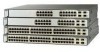
Caution For detailed instructions on removing the SFP modules, refer to your normal board and component handling procedures. 3-48 Catalyst 3750 Switch Hardware Installation Guide 78-15136-02 Connecting to an SFP Module Chapter 3 Switch Installation 86550 86550 Figure 3-41 Connecting to a 1000BASE-T SFP module: Caution To prevent ESD damage, follow your SFP documentation...Category 5 cable to an SFP Module Port 0 SERIES 23X 13 13X 14 15 16 17 18 19 2024X 21 22 23 1 24 23X 114X 24X 2 Catalyst 3750 SERIES 1 2 1 1 LC connector Step 5 If necessary, reconfigure and restart the...
Caution For detailed instructions on removing the SFP modules, refer to your normal board and component handling procedures. 3-48 Catalyst 3750 Switch Hardware Installation Guide 78-15136-02 Connecting to an SFP Module Chapter 3 Switch Installation 86550 86550 Figure 3-41 Connecting to a 1000BASE-T SFP module: Caution To prevent ESD damage, follow your SFP documentation...Category 5 cable to an SFP Module Port 0 SERIES 23X 13 13X 14 15 16 17 18 19 2024X 21 22 23 1 24 23X 114X 24X 2 Catalyst 3750 SERIES 1 2 1 1 LC connector Step 5 If necessary, reconfigure and restart the...
Hardware Installation Guide
Page 192
... StackWise cables cable numbers 2-15 connecting to 3-37 cautions xvi chassis warning, rack-mounting and servicing E-19 Cisco IP Phones, connecting to 3-45 Cisco RPS See RPS CiscoView 2-18 CLI 2-18 accessing by using Express Setup D-2 accessing through console port D-3 ...48 connectivity problems, solving 4-3 connectors and cables 10/100/1000 ports B-1 to B-2 10/100 ports B-3 to B-4 console port B-6 to B-11 power (AC and RPS) 2-16 SC connectors B-5 SFP module ports B-5 See also cables console port connecting to 3-8, D-7 connectors and cables B-6 to B-11 described 2-17 IN-2 Catalyst 3750 Switch...
... StackWise cables cable numbers 2-15 connecting to 3-37 cautions xvi chassis warning, rack-mounting and servicing E-19 Cisco IP Phones, connecting to 3-45 Cisco RPS See RPS CiscoView 2-18 CLI 2-18 accessing by using Express Setup D-2 accessing through console port D-3 ...48 connectivity problems, solving 4-3 connectors and cables 10/100/1000 ports B-1 to B-2 10/100 ports B-3 to B-4 console port B-6 to B-11 power (AC and RPS) 2-16 SC connectors B-5 SFP module ports B-5 See also cables console port connecting to 3-8, D-7 connectors and cables B-6 to B-11 described 2-17 IN-2 Catalyst 3750 Switch...
Hardware Installation Guide
Page 195
... 1-4 power connecting to 3-10 connectors 2-14, 2-16 specifications A-1 to A-5 power on 3-10 power supply AC power outlet 2-16 RPS connector 2-16 procedures connection 3-44 to 3-48 installation 3-17 to 3-36 product disposal warning E-17 publications, related xxi Q qualified personnel warning E-4 R rack-mounting 3-18 to 3-36 rear panel clearance 3-6 description 2-14 to...
... 1-4 power connecting to 3-10 connectors 2-14, 2-16 specifications A-1 to A-5 power on 3-10 power supply AC power outlet 2-16 RPS connector 2-16 procedures connection 3-44 to 3-48 installation 3-17 to 3-36 product disposal warning E-17 publications, related xxi Q qualified personnel warning E-4 R rack-mounting 3-18 to 3-36 rear panel clearance 3-6 description 2-14 to...
