
Service Manual
Page 3
... be disassembled/assembled and adjusted. Appendix contains a general timing chart and general circuit diagrams. COPYRIGHT © 1999 CANON INC. Chapter 6 Fixing System discusses the principles of operation used for the machine's pickup/feeding system. It also... Formation System discusses the principles of maintenance/inspection, standards/ adjustments, and problem identification (image fault/malfunction). Chapter 11 Troubleshooting provides tables of operation used for the machine's image formation system. Chapter 7 Externals/Auxiliary Mechanisms discusses the principles of...
... be disassembled/assembled and adjusted. Appendix contains a general timing chart and general circuit diagrams. COPYRIGHT © 1999 CANON INC. Chapter 6 Fixing System discusses the principles of operation used for the machine's pickup/feeding system. It also... Formation System discusses the principles of maintenance/inspection, standards/ adjustments, and problem identification (image fault/malfunction). Chapter 11 Troubleshooting provides tables of operation used for the machine's image formation system. Chapter 7 Externals/Auxiliary Mechanisms discusses the principles of...
Service Manual
Page 10
...82 E. GENERAL CIRCUIT DIAGRAM A-5 D. DC CONTROLLER CIRCUIT DIAGRAM A-7 E. Electrical 11-41 III. Troubleshooting Image Faults 11-53 IV. A-1 B. BLANK EXPOSURE (front) CIRCUIT DIAGRAM A-33 M. CANON PC800s/900s REV.0 AUG. 1999 PRINTED IN JAPAN (IMPRIME AU JAPON) STANDARDS AND ADJUSTMENTS 11-5... CIRCUIT DIAGRAM A-31 K. AE SENSOR CIRCUIT DIAGRAM A-29 I . Troubleshooting Malfunctions 11-61 V. ARRANGEMENT AND FUNCTIONS OF ELECTRICAL PARTS 11-79 A. SOLVENTS/OILS A-36 viii COPYRIGHT © 1999 CANON INC. SELF DIAGNOSIS 11-86 APPENDIX A. SPECIAL TOOLS A-35 O. ...
...82 E. GENERAL CIRCUIT DIAGRAM A-5 D. DC CONTROLLER CIRCUIT DIAGRAM A-7 E. Electrical 11-41 III. Troubleshooting Image Faults 11-53 IV. A-1 B. BLANK EXPOSURE (front) CIRCUIT DIAGRAM A-33 M. CANON PC800s/900s REV.0 AUG. 1999 PRINTED IN JAPAN (IMPRIME AU JAPON) STANDARDS AND ADJUSTMENTS 11-5... CIRCUIT DIAGRAM A-31 K. AE SENSOR CIRCUIT DIAGRAM A-29 I . Troubleshooting Malfunctions 11-61 V. ARRANGEMENT AND FUNCTIONS OF ELECTRICAL PARTS 11-79 A. SOLVENTS/OILS A-36 viii COPYRIGHT © 1999 CANON INC. SELF DIAGNOSIS 11-86 APPENDIX A. SPECIAL TOOLS A-35 O. ...
Service Manual
Page 264
...Solenoids .... 11-79 B. PCBs 11-82 E. CANON PC800s/900s REV.0 AUG. 1999 PRINTED IN JAPAN (IMPRIME AU JAPON) Electrical 11-41 III. TROUBLESHOOTING MALFUNCTIONS 11-61 A. Faulty Feeding 11-78 VI. TROUBLESHOOTING FEEDING PROBLEMS 11-75 A. STANDARDS AND ADJUSTMENTS 11-5... A. Sample Image Faults ....... 11-52 C. SELF DIAGNOSIS 11-86 COPYRIGHT © 1999 CANON INC. Variable Resistors (VR...
...Solenoids .... 11-79 B. PCBs 11-82 E. CANON PC800s/900s REV.0 AUG. 1999 PRINTED IN JAPAN (IMPRIME AU JAPON) Electrical 11-41 III. TROUBLESHOOTING MALFUNCTIONS 11-61 A. Faulty Feeding 11-78 VI. TROUBLESHOOTING FEEDING PROBLEMS 11-75 A. STANDARDS AND ADJUSTMENTS 11-5... A. Sample Image Faults ....... 11-52 C. SELF DIAGNOSIS 11-86 COPYRIGHT © 1999 CANON INC. Variable Resistors (VR...
Service Manual
Page 266
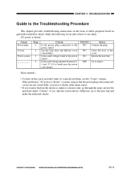
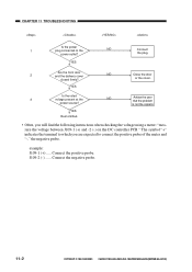
... fault) of a specific problem, see the "Cause" column. Otherwise, go through the steps: answer the questions under "Checks"; COPYRIGHT © 1999 CANON INC. Is the rated voltage found near the power cord mount.) YES/NO NO NO NO YES Action Connect the plug. if yes, take , go...to the next step and make or action to take the action shown. CANON PC800s/900s REV.0 AUG. 1999 PRINTED IN JAPAN (IMPRIME AU JAPON) 11-1 CHAPTER 11 TROUBLESHOOTING Guide to the Troubleshooting Procedure This chapter provides troubleshooting instructions in the form of how to use them: AC power is absent....
... fault) of a specific problem, see the "Cause" column. Otherwise, go through the steps: answer the questions under "Checks"; COPYRIGHT © 1999 CANON INC. Is the rated voltage found near the power cord mount.) YES/NO NO NO NO YES Action Connect the plug. if yes, take , go...to the next step and make or action to take the action shown. CANON PC800s/900s REV.0 AUG. 1999 PRINTED IN JAPAN (IMPRIME AU JAPON) 11-1 CHAPTER 11 TROUBLESHOOTING Guide to the Troubleshooting Procedure This chapter provides troubleshooting instructions in the form of how to use them: AC power is absent....
Service Manual
Page 267
... not the copier's. YES Rest omitted. • Often, you are expected to the NO power outlet? example: J109-1 (+) ..... CANON PC800s/900s REV.0 AUG. 1999 PRINTED IN JAPAN (IMPRIME AU JAPON) CHAPTER 11 TROUBLESHOOTING Is the power 1 plug connected to connect the positive probe of the meter and "-," the negative probe. YES 3 Is... the voltage between J109-1 (+) and -2 (-) on the DC controller PCB." Connect the positive probe. or the cover. Connect the negative probe. 11-2 COPYRIGHT © 1999 CANON INC.
... not the copier's. YES Rest omitted. • Often, you are expected to the NO power outlet? example: J109-1 (+) ..... CANON PC800s/900s REV.0 AUG. 1999 PRINTED IN JAPAN (IMPRIME AU JAPON) CHAPTER 11 TROUBLESHOOTING Is the power 1 plug connected to connect the positive probe of the meter and "-," the negative probe. YES 3 Is... the voltage between J109-1 (+) and -2 (-) on the DC controller PCB." Connect the positive probe. or the cover. Connect the negative probe. 11-2 COPYRIGHT © 1999 CANON INC.
Service Manual
Page 268
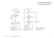
...Fogging of difference between front and rear (Note 2) 3. Cartridge 2. DC controller PCB 5. Composite power supply PCB (See the appropriate troubleshooting procedure.) END Note: 1. See p. 11-42. COPYRIGHT © 1999 CANON INC. Presence/absence of background (Note 2) I. Density of gray scale No. 1 (good or bad; Note 2) 4. Scanning system... 1) NO YES Is the optimum density obtained by intensity adjustment? (Note 3) NO YES Check the following : 1. See the appropriate troubleshooting procedure. 3. CANON PC800s/900s REV.0 AUG. 1999 PRINTED IN JAPAN (IMPRIME AU JAPON) 11-3
...Fogging of difference between front and rear (Note 2) 3. Cartridge 2. DC controller PCB 5. Composite power supply PCB (See the appropriate troubleshooting procedure.) END Note: 1. See p. 11-42. COPYRIGHT © 1999 CANON INC. Presence/absence of background (Note 2) I. Density of gray scale No. 1 (good or bad; Note 2) 4. Scanning system... 1) NO YES Is the optimum density obtained by intensity adjustment? (Note 3) NO YES Check the following : 1. See the appropriate troubleshooting procedure. 3. CANON PC800s/900s REV.0 AUG. 1999 PRINTED IN JAPAN (IMPRIME AU JAPON) 11-3

Service Manual
Page 270
...Turn VR105 on the DC controller PCB so that the leading edge non-image width is 2.0 ±1.5 mm when the Test Sheet is as indicated. CANON PC800s/900s REV.0 AUG. 1999 PRINTED IN JAPAN (IMPRIME AU JAPON) 11-5 Copier a. VR105 J131 J101 J102 J101 J130 J114 J102 VR104VR105VR106 VR107 ... Edge Non-Image Width Direction of VR105 Clockwise Counterclockwise Leading edge non-image width Decreases Increases Table 11-201 COPYRIGHT © 1999 CANON INC. Leading Edge Non-Image Width Make adjustments so that the width is copied in Direct. STANDARDS AND ADJUSTMENTS A. CHAPTER 11...
...Turn VR105 on the DC controller PCB so that the leading edge non-image width is 2.0 ±1.5 mm when the Test Sheet is as indicated. CANON PC800s/900s REV.0 AUG. 1999 PRINTED IN JAPAN (IMPRIME AU JAPON) 11-5 Copier a. VR105 J131 J101 J102 J101 J130 J114 J102 VR104VR105VR106 VR107 ... Edge Non-Image Width Direction of VR105 Clockwise Counterclockwise Leading edge non-image width Decreases Increases Table 11-201 COPYRIGHT © 1999 CANON INC. Leading Edge Non-Image Width Make adjustments so that the width is copied in Direct. STANDARDS AND ADJUSTMENTS A. CHAPTER 11...

Service Manual
Page 271
... 1) Turn VR104 on the DC controller PCB so that the leading edge margin is 2.5 ±1.5 mm when the Test Sheet is as indicated. CHAPTER 11 TROUBLESHOOTING b. CANON PC800s/900s REV.0 AUG. 1999 PRINTED IN JAPAN (IMPRIME AU JAPON)
... 1) Turn VR104 on the DC controller PCB so that the leading edge margin is 2.5 ±1.5 mm when the Test Sheet is as indicated. CHAPTER 11 TROUBLESHOOTING b. CANON PC800s/900s REV.0 AUG. 1999 PRINTED IN JAPAN (IMPRIME AU JAPON)

Service Manual
Page 272
.... Reference: 1. "Removing the Copyboard Glass".) 3) Loosen the screws used to become slack, requiring adjustment. 2. CANON PC800s/900s REV.0 AUG. 1999 PRINTED IN JAPAN (IMPRIME AU JAPON) 11-7 CHAPTER 11 TROUBLESHOOTING c. Adjusting the Mirror Position (optical length between the No. 1 mirror and the No. 2 mirror is not correct, the horizontal reproduction ratio will...
.... Reference: 1. "Removing the Copyboard Glass".) 3) Loosen the screws used to become slack, requiring adjustment. 2. CANON PC800s/900s REV.0 AUG. 1999 PRINTED IN JAPAN (IMPRIME AU JAPON) 11-7 CHAPTER 11 TROUBLESHOOTING c. Adjusting the Mirror Position (optical length between the No. 1 mirror and the No. 2 mirror is not correct, the horizontal reproduction ratio will...

Service Manual
Page 273
CANON PC800s/900s REV.0 AUG. 1999 PRINTED IN JAPAN (IMPRIME AU JAPON) CHAPTER 11 TROUBLESHOOTING 4) Turn the cable drive pulley [3] so that the three shafts [2] of the mirror positioning tool for the front and the rear may be arranged as shown. [2] [3] [2] Figure 11-207 (rear) [2] [2] Figure 11-208 (front) 11-8 COPYRIGHT © 1999 CANON INC.
CANON PC800s/900s REV.0 AUG. 1999 PRINTED IN JAPAN (IMPRIME AU JAPON) CHAPTER 11 TROUBLESHOOTING 4) Turn the cable drive pulley [3] so that the three shafts [2] of the mirror positioning tool for the front and the rear may be arranged as shown. [2] [3] [2] Figure 11-207 (rear) [2] [2] Figure 11-208 (front) 11-8 COPYRIGHT © 1999 CANON INC.

Service Manual
Page 274
CANON PC800s/900s REV.0 AUG. 1999 PRINTED IN JAPAN (IMPRIME AU JAPON) 11-9 CHAPTER 11 TROUBLESHOOTING 5) While keeping the condition of 4), tighten the positioning screw at the rear and the front of the No. 1 mirror mount [1]. [1] Figure 11-209 (rear) [1] Figure 11-210 (front) COPYRIGHT © 1999 CANON INC.
CANON PC800s/900s REV.0 AUG. 1999 PRINTED IN JAPAN (IMPRIME AU JAPON) 11-9 CHAPTER 11 TROUBLESHOOTING 5) While keeping the condition of 4), tighten the positioning screw at the rear and the front of the No. 1 mirror mount [1]. [1] Figure 11-209 (rear) [1] Figure 11-210 (front) COPYRIGHT © 1999 CANON INC.

Service Manual
Page 275
..., pickup faults or the like can occur. Spring gauge (CK-0054) Holding plate 18mm Cassette spring Cassette Figure 11-211 11-10 COPYRIGHT © 1999 CANON INC. If a fault is suspected, check the force of the spring using a spring gauge (CK-0054), and replace the spring if it is not as... up the holding plate is 18 mm away from the bottom of the cassette is 970 ±150 g when the holding plate of the cassette. CANON PC800s/900s REV.0 AUG. 1999 PRINTED IN JAPAN (IMPRIME AU JAPON) CHAPTER 11 TROUBLESHOOTING d.
..., pickup faults or the like can occur. Spring gauge (CK-0054) Holding plate 18mm Cassette spring Cassette Figure 11-211 11-10 COPYRIGHT © 1999 CANON INC. If a fault is suspected, check the force of the spring using a spring gauge (CK-0054), and replace the spring if it is not as... up the holding plate is 18 mm away from the bottom of the cassette is 970 ±150 g when the holding plate of the cassette. CANON PC800s/900s REV.0 AUG. 1999 PRINTED IN JAPAN (IMPRIME AU JAPON) CHAPTER 11 TROUBLESHOOTING d.

Service Manual
Page 276
Routing the Scanner Drive Cable CHAPTER 11 TROUBLESHOOTING Wind 1.5 times. (black cable) Wind 7.5 times. (silvercolored cable) Figure 11-212 COPYRIGHT © 1999 CANON INC. CANON PC800s/900s REV.0 AUG. 1999 PRINTED IN JAPAN (IMPRIME AU JAPON) 11-11 e-1.
Routing the Scanner Drive Cable CHAPTER 11 TROUBLESHOOTING Wind 1.5 times. (black cable) Wind 7.5 times. (silvercolored cable) Figure 11-212 COPYRIGHT © 1999 CANON INC. CANON PC800s/900s REV.0 AUG. 1999 PRINTED IN JAPAN (IMPRIME AU JAPON) 11-11 e-1.

Service Manual
Page 277
... Work Prepare the following: • Mirror positioning tool (FY9-3009) • Cable clip (FY9-3017) • Adhesive tape 1) Set the mirror positioning tool as shown. CANON PC800s/900s REV.0 AUG. 1999 PRINTED IN JAPAN (IMPRIME AU JAPON) Routing the Scanner Drive Cable 1. Figure 11-213 2) Prepare about five strips of adhesive.... (See Chapter 7.III.C.1."Removing the Copyboard Glass.") 4) Disconnect the connectors (J101, J131) [1] from the DC controller PCB. 11-12 [1] Figure 11-214 COPYRIGHT © 1999 CANON INC. CHAPTER 11 TROUBLESHOOTING e-2.
... Work Prepare the following: • Mirror positioning tool (FY9-3009) • Cable clip (FY9-3017) • Adhesive tape 1) Set the mirror positioning tool as shown. CANON PC800s/900s REV.0 AUG. 1999 PRINTED IN JAPAN (IMPRIME AU JAPON) Routing the Scanner Drive Cable 1. Figure 11-213 2) Prepare about five strips of adhesive.... (See Chapter 7.III.C.1."Removing the Copyboard Glass.") 4) Disconnect the connectors (J101, J131) [1] from the DC controller PCB. 11-12 [1] Figure 11-214 COPYRIGHT © 1999 CANON INC. CHAPTER 11 TROUBLESHOOTING e-2.

Service Manual
Page 278
CHAPTER 11 TROUBLESHOOTING 5) If the machine is equipped with an ADF, free the hook [2], and disconnect the two relay connectors [3] from the left upper stay [4]. [3] [2] [2] [4] [2] [2] [3] Figure 11-215 6) Remove the three screws [5], and detach the left upper stay [4]. [5] [5] [4] Figure 11-216 COPYRIGHT © 1999 CANON INC. CANON PC800s/900s REV.0 AUG. 1999 PRINTED IN JAPAN (IMPRIME AU JAPON) 11-13
CHAPTER 11 TROUBLESHOOTING 5) If the machine is equipped with an ADF, free the hook [2], and disconnect the two relay connectors [3] from the left upper stay [4]. [3] [2] [2] [4] [2] [2] [3] Figure 11-215 6) Remove the three screws [5], and detach the left upper stay [4]. [5] [5] [4] Figure 11-216 COPYRIGHT © 1999 CANON INC. CANON PC800s/900s REV.0 AUG. 1999 PRINTED IN JAPAN (IMPRIME AU JAPON) 11-13

Service Manual
Page 279
CANON PC800s/900s REV.0 AUG. 1999 PRINTED IN JAPAN (IMPRIME AU JAPON) CHAPTER 11 TROUBLESHOOTING 7) Remove the four screws [7], and detach the lens cover [8]. [7] [7] [8] Figure 11-217 11-14 COPYRIGHT © 1999 CANON INC.
CANON PC800s/900s REV.0 AUG. 1999 PRINTED IN JAPAN (IMPRIME AU JAPON) CHAPTER 11 TROUBLESHOOTING 7) Remove the four screws [7], and detach the lens cover [8]. [7] [7] [8] Figure 11-217 11-14 COPYRIGHT © 1999 CANON INC.

Service Manual
Page 280
CHAPTER 11 TROUBLESHOOTING 2. CANON PC800s/900s REV.0 AUG. 1999 PRINTED IN JAPAN (IMPRIME AU JAPON) 11-15 Routing the Reversing Cable 1) Wind the reversing cables (silver-colored) [2] on top; then, secure it in position with a cable clip [3]. [1] Longer end Shorter end [2] Face with the longer of the two on the cable drive pulley [1] 7.5 times with a marking Figure 11-218 [1] [3] [3] Top view Figure 11-219 COPYRIGHT © 1999 CANON INC.
CHAPTER 11 TROUBLESHOOTING 2. CANON PC800s/900s REV.0 AUG. 1999 PRINTED IN JAPAN (IMPRIME AU JAPON) 11-15 Routing the Reversing Cable 1) Wind the reversing cables (silver-colored) [2] on top; then, secure it in position with a cable clip [3]. [1] Longer end Shorter end [2] Face with the longer of the two on the cable drive pulley [1] 7.5 times with a marking Figure 11-218 [1] [3] [3] Top view Figure 11-219 COPYRIGHT © 1999 CANON INC.

Service Manual
Page 281
CHAPTER 11 TROUBLESHOOTING 2) Put the cable drive pulley [1] into the shaft, be sure that the hook is at the front. [5] Hook [1] (front) [4] Figure 11-220 3) Hook the shorter end [6] on the pulley [7]. [7] [6] Figure 11-221 11-16 COPYRIGHT © 1999 CANON INC. When putting the cable drive pulley into the shaft [4], and secure it in position with an E-ring [5]. CANON PC800s/900s REV.0 AUG. 1999 PRINTED IN JAPAN (IMPRIME AU JAPON)
CHAPTER 11 TROUBLESHOOTING 2) Put the cable drive pulley [1] into the shaft, be sure that the hook is at the front. [5] Hook [1] (front) [4] Figure 11-220 3) Hook the shorter end [6] on the pulley [7]. [7] [6] Figure 11-221 11-16 COPYRIGHT © 1999 CANON INC. When putting the cable drive pulley into the shaft [4], and secure it in position with an E-ring [5]. CANON PC800s/900s REV.0 AUG. 1999 PRINTED IN JAPAN (IMPRIME AU JAPON)

Service Manual
Page 282
... the shorter end [6] on the cable hook [12], secure its end with adhesive tape [13]. CHAPTER 11 TROUBLESHOOTING 4) Lead the shorter end [6] under the No. 1 mirror mount [8] and the No. 2/3 mirror mount [9]; CANON PC800s/900s REV.0 AUG. 1999 PRINTED IN JAPAN (IMPRIME AU JAPON) 11-17 Be sure that the secured... end of the cable is found where the hole in the left rear pulley [10] and the pulley [11] of the cable matches. [13] [12] [6] Figure 11-223 COPYRIGHT © 1999 CANON INC...
... the shorter end [6] on the cable hook [12], secure its end with adhesive tape [13]. CHAPTER 11 TROUBLESHOOTING 4) Lead the shorter end [6] under the No. 1 mirror mount [8] and the No. 2/3 mirror mount [9]; CANON PC800s/900s REV.0 AUG. 1999 PRINTED IN JAPAN (IMPRIME AU JAPON) 11-17 Be sure that the secured... end of the cable is found where the hole in the left rear pulley [10] and the pulley [11] of the cable matches. [13] [12] [6] Figure 11-223 COPYRIGHT © 1999 CANON INC...

Service Manual
Page 283
CANON PC800s/900s REV.0 AUG. 1999 PRINTED IN JAPAN (IMPRIME AU JAPON) CHAPTER 11 TROUBLESHOOTING 6) Lead the longer end [14] along the cable drive pulley, and hook it on the pulley [16] on the right front side. [14] [15] [1] Figure 11-224 7) Lead the longer end [14] under the No. 1 mirror mount [8] and the No. 2/3 mirror mount [9]; then, hook it on the pulley [15] on the left front side and the pulley [17] of the No. 2/3 mirror mount. [17] [8] [16] [14] [9] Figure 11-225 11-18 COPYRIGHT © 1999 CANON INC.
CANON PC800s/900s REV.0 AUG. 1999 PRINTED IN JAPAN (IMPRIME AU JAPON) CHAPTER 11 TROUBLESHOOTING 6) Lead the longer end [14] along the cable drive pulley, and hook it on the pulley [16] on the right front side. [14] [15] [1] Figure 11-224 7) Lead the longer end [14] under the No. 1 mirror mount [8] and the No. 2/3 mirror mount [9]; then, hook it on the pulley [15] on the left front side and the pulley [17] of the No. 2/3 mirror mount. [17] [8] [16] [14] [9] Figure 11-225 11-18 COPYRIGHT © 1999 CANON INC.
