

Instruction Manual - English
Page 2
... 1 1 2 3 3 3 3 4 4 5 5 6 6 7 8 9 99 10 10 11 11 12 12 12 13 13 13 14 14 15 15 16 17 17 18 19 20 20 21 22 23 LS2-F52A Threading the upper thread 5-6. Adjusting the positions of the needle and needle hole of the feed dog 8-3. Adjusting the clearance between the needle and hook.... Installing the spool pin 4-5. Adjusting the timing of the vibrating presser foot 9. Lubrication 4-11. STANDARD ADJUSTMENTS 8-1. Adjusting the presser foot movement amount 8-12. CONTENTS 1. MAIN PARTS NAMES 2. Checking the machine pulley rotating direction 5. Sewing 6-2.
... 1 1 2 3 3 3 3 4 4 5 5 6 6 7 8 9 99 10 10 11 11 12 12 12 13 13 13 14 14 15 15 16 17 17 18 19 20 20 21 22 23 LS2-F52A Threading the upper thread 5-6. Adjusting the positions of the needle and needle hole of the feed dog 8-3. Adjusting the clearance between the needle and hook.... Installing the spool pin 4-5. Adjusting the timing of the vibrating presser foot 9. Lubrication 4-11. STANDARD ADJUSTMENTS 8-1. Adjusting the presser foot movement amount 8-12. CONTENTS 1. MAIN PARTS NAMES 2. Checking the machine pulley rotating direction 5. Sewing 6-2.

Instruction Manual - English
Page 3
SPECIFICATIONS 1. stitch length Feed dog height Needles Presser bar lifter knee lifter Medium-thick materials - MAIN PARTS NAMES 2. SPECIFICATIONS Use Sewing speed Presser foot height Max. very thick materials 2,200 spm 8.5 mm 14 mm 10 mm 1 mm DP X 17 1 LS2-F52A MAIN PARTS NAMES Needle bar Finger guard A C) Vibrating presser foot Lifting presser foot Feed dog Feed regulating dial Pulley 0 Belt guard Reverse lever Bobbin winder Safety clutch mechanism e O 2. 1.
SPECIFICATIONS 1. stitch length Feed dog height Needles Presser bar lifter knee lifter Medium-thick materials - MAIN PARTS NAMES 2. SPECIFICATIONS Use Sewing speed Presser foot height Max. very thick materials 2,200 spm 8.5 mm 14 mm 10 mm 1 mm DP X 17 1 LS2-F52A MAIN PARTS NAMES Needle bar Finger guard A C) Vibrating presser foot Lifting presser foot Feed dog Feed regulating dial Pulley 0 Belt guard Reverse lever Bobbin winder Safety clutch mechanism e O 2. 1.

Instruction Manual - English
Page 4
.... Sewing speed 2,000 spm Frequency 50 Hz 60 Hz Motor pulley Motor pulley 55 Motor pulley 50 V-belt 42 inches 42 inches -2 LS2-F52A Work table processing diagram Head rest hole Motor mounting holes Thread stand hole 50 026 Seat depth 1 Knee lifter installation position co 57=o3...• Motor a CAUTION O• All cords which corresponds to the motor being used. • Select the correct motor from ® any moving parts. Power Single-phase 110V Three-phase 220V Motor 2pole, 400W motor 2pole, 400W motor • Select the correct motor pulley and V-belt by another ...
.... Sewing speed 2,000 spm Frequency 50 Hz 60 Hz Motor pulley Motor pulley 55 Motor pulley 50 V-belt 42 inches 42 inches -2 LS2-F52A Work table processing diagram Head rest hole Motor mounting holes Thread stand hole 50 026 Seat depth 1 Knee lifter installation position co 57=o3...• Motor a CAUTION O• All cords which corresponds to the motor being used. • Select the correct motor from ® any moving parts. Power Single-phase 110V Three-phase 220V Motor 2pole, 400W motor 2pole, 400W motor • Select the correct motor pulley and V-belt by another ...
Instruction Manual - English
Page 9
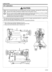
...Use only the lubricating oil (Nisseki Sewing Lube 10) specified by the arrows. Add oil to other sliding parts also, while being careful to wear protective goggles and gloves when handling the lubricating oil, so that no oil...do not drink the oil under any circumstances, as it is pressed by mistake, which could result in the places indicated by Brother. • Add 1-2 drops of non-use . INSTALLATION 4-10. Lubrication A CAUTION ® • Do not connect... lubricated and the oil supply replenished before it can result. FIT ) I L, 0 O 0 ( ) OF 6 \CD 0 7 LS2-F52A 4.
...Use only the lubricating oil (Nisseki Sewing Lube 10) specified by the arrows. Add oil to other sliding parts also, while being careful to wear protective goggles and gloves when handling the lubricating oil, so that no oil...do not drink the oil under any circumstances, as it is pressed by mistake, which could result in the places indicated by Brother. • Add 1-2 drops of non-use . INSTALLATION 4-10. Lubrication A CAUTION ® • Do not connect... lubricated and the oil supply replenished before it can result. FIT ) I L, 0 O 0 ( ) OF 6 \CD 0 7 LS2-F52A 4.

Instruction Manual - English
Page 10
...oiling adjustments completed, tighten the nut securely. 4-11. Checking the machine pulley rotating direction A CAUTION • Do not touch any of the arrow 0. LS2-F52A After pouring oil, tighten the oil plug Q securely. ■ Oiling adjustment to the machine. 1. To increase oil flow, loosen the adjusting screw 0, ...tighten the screw G. Depress the treadle and check that the direction of rotation of the machine pulley matches the direction of the moving parts or place any objects against the machine while sewing, as this may result in personal injury or damage to hook 9 Loosen the ...
...oiling adjustments completed, tighten the nut securely. 4-11. Checking the machine pulley rotating direction A CAUTION • Do not touch any of the arrow 0. LS2-F52A After pouring oil, tighten the oil plug Q securely. ■ Oiling adjustment to the machine. 1. To increase oil flow, loosen the adjusting screw 0, ...tighten the screw G. Depress the treadle and check that the direction of rotation of the machine pulley matches the direction of the moving parts or place any objects against the machine while sewing, as this may result in personal injury or damage to hook 9 Loosen the ...

Instruction Manual - English
Page 12
... the bobbin case and insert the bobbin case into the bobbin case. 2. Winding the lower thread A CAUTION • Do not touch any of the moving parts or place any objects against the machine while winding the lower thread, as a result of the bobbin capacity. O 2. IrJr. te4. 4:zzimmztp, or) 0A...of thread wound onto the bobbin should be wound on the power switch. 4- Push down the bobbin set lever 0 will then start. 7. LS2-F52A While holding the bobbin so that the bobbin turns clockwise when the thread is completed, the bobbin set lever O. 5. Installing the bobbin case Note...
... the bobbin case and insert the bobbin case into the bobbin case. 2. Winding the lower thread A CAUTION • Do not touch any of the moving parts or place any objects against the machine while winding the lower thread, as a result of the bobbin capacity. O 2. IrJr. te4. 4:zzimmztp, or) 0A...of thread wound onto the bobbin should be wound on the power switch. 4- Push down the bobbin set lever 0 will then start. 7. LS2-F52A While holding the bobbin so that the bobbin turns clockwise when the thread is completed, the bobbin set lever O. 5. Installing the bobbin case Note...

Instruction Manual - English
Page 14
... you until the motor stops fully before using the machine and when leaving the machine unattended 11,• Do not touch any of the moving parts or place any objects against the machine while sewing, as a result of the motor's inertia. SEWING 6. SEWING A CAUTION • Attach... machine may result personal injury or damage to normal. -12- Pull the lower thread toward you and check that it pulls out smoothly. 3. LS2-F52A Wait until the lower thread comes out onto the feed dog. Lower thread wo Lower thread 6-2. Depress the treadle to start sewing. Backtacking 2. While...
... you until the motor stops fully before using the machine and when leaving the machine unattended 11,• Do not touch any of the moving parts or place any objects against the machine while sewing, as a result of the motor's inertia. SEWING 6. SEWING A CAUTION • Attach... machine may result personal injury or damage to normal. -12- Pull the lower thread toward you and check that it pulls out smoothly. 3. LS2-F52A Wait until the lower thread comes out onto the feed dog. Lower thread wo Lower thread 6-2. Depress the treadle to start sewing. Backtacking 2. While...

Instruction Manual - English
Page 16
...and check that they operate correctly before starting work. • When carrying out inspection, adjustment and maintenance • When replacing consumable parts such as a result of the motor's inertia. Loosen the tension thumb nut Q and screw 9. 2. Adjusting the thread controller ...qualified personnel. 0 • Ask your Brother dealer or a qualified electrician to carry out any maintenance and inspection of the sewing machine should only be absolutely sure to re-install them to observe all safety precautions. 8-1. LS2-F52A 8. STANDARD ADJUSTMENTS A CAUTION (30•...
...and check that they operate correctly before starting work. • When carrying out inspection, adjustment and maintenance • When replacing consumable parts such as a result of the motor's inertia. Loosen the tension thumb nut Q and screw 9. 2. Adjusting the thread controller ...qualified personnel. 0 • Ask your Brother dealer or a qualified electrician to carry out any maintenance and inspection of the sewing machine should only be absolutely sure to re-install them to observe all safety precautions. 8-1. LS2-F52A 8. STANDARD ADJUSTMENTS A CAUTION (30•...

Instruction Manual - English
Page 21
Adjusting the Clearance between the two parts is indicated by means of movement of screws 0 which is 0.7-0.9mm. 3. Adjust the clearance between projection of hook 0, and the opener 0 by "S" on its travel. 2. ... 8-8. The standard clearance between rotary hook and opener (Thread release finger) The opener facilitates the passage of the needle thread loop by loosening the screw 0. 3. LS2-F52A IN Adjustment of it.
Adjusting the Clearance between the two parts is indicated by means of movement of screws 0 which is 0.7-0.9mm. 3. Adjust the clearance between projection of hook 0, and the opener 0 by "S" on its travel. 2. ... 8-8. The standard clearance between rotary hook and opener (Thread release finger) The opener facilitates the passage of the needle thread loop by loosening the screw 0. 3. LS2-F52A IN Adjustment of it.

