Owner's guide
Page 2
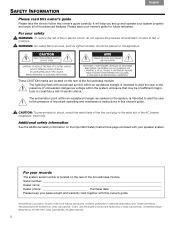
...prior written permission. CAUTION: To prevent electric shock, match the wide blade of the line cord plug to the presence of the Acoustimass module. Serial number Dealer name Dealer phone Purchase date Please keep your sales receipt and warranty card together with your speaker system. ... ! WARNING: No naked flame sources, such as marked on the Important Safety Instructions page enclosed with this owner's guide. ©2006 Bose Corporation. Additional safety information See the additional safety information on the system, is intended to alert the user to the wide slot of Dolby...
...prior written permission. CAUTION: To prevent electric shock, match the wide blade of the line cord plug to the presence of the Acoustimass module. Serial number Dealer name Dealer phone Purchase date Please keep your sales receipt and warranty card together with your speaker system. ... ! WARNING: No naked flame sources, such as marked on the Important Safety Instructions page enclosed with this owner's guide. ©2006 Bose Corporation. Additional safety information See the additional safety information on the system, is intended to alert the user to the wide slot of Dolby...
Owner's guide
Page 3
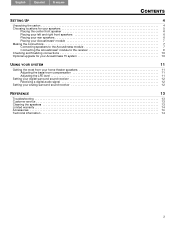
... your left and right front speakers 6 Placing your rear speakers 6 Placing your Acoustimass® module 7 Making the connections 7 Connecting speakers to the Acoustimass module 7 Connecting the Acoustimass® module to the receiver 9 Checking and finalizing connections 10 Optional upgrade for your Acoustimass 15 system 10 USING YOUR SYSTEM 11 Getting the most from your...
... your left and right front speakers 6 Placing your rear speakers 6 Placing your Acoustimass® module 7 Making the connections 7 Connecting speakers to the Acoustimass module 7 Connecting the Acoustimass® module to the receiver 9 Checking and finalizing connections 10 Optional upgrade for your Acoustimass 15 system 10 USING YOUR SYSTEM 11 Getting the most from your...
Owner's guide
Page 4
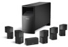
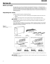
... Carton contents 20-ft (6.1 m) system input cable Acoustimass module Rubber feet With Acoustimass 15 Series IIl system Three 20-ft (6.1 m) front speaker cables With Acoustimass 16 Series II system Four cube array speakers Center front speaker Two 50...Bose directly, refer to record the serial number for a powerful and realistic home theater experience. Français Español English SETTING UP Before you begin We appreciate your authorized Bose dealer. carton and contact your choice of this guide and on page 2 of the Bose® Acoustimass® 16 Series II or 15 Series...
... Carton contents 20-ft (6.1 m) system input cable Acoustimass module Rubber feet With Acoustimass 15 Series IIl system Three 20-ft (6.1 m) front speaker cables With Acoustimass 16 Series II system Four cube array speakers Center front speaker Two 50...Bose directly, refer to record the serial number for a powerful and realistic home theater experience. Français Español English SETTING UP Before you begin We appreciate your authorized Bose dealer. carton and contact your choice of this guide and on page 2 of the Bose® Acoustimass® 16 Series II or 15 Series...
Owner's guide
Page 5
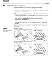
...TV. • The cube speaker arrays in your system are provided for attachment to the bottom of speaker locations. theater setup. Figure 2 Acoustimass 16 system Sample speaker placement a. To prevent this problem, rubber feet are identical and can be used interchangeably. • The top and bottom ...cubes of each of charge, by contacting Bose. English Español Français SETTING UP Choosing locations for your speakers Keep these guidelines in mind when choosing a location for...
...TV. • The cube speaker arrays in your system are provided for attachment to the bottom of speaker locations. theater setup. Figure 2 Acoustimass 16 system Sample speaker placement a. To prevent this problem, rubber feet are identical and can be used interchangeably. • The top and bottom ...cubes of each of charge, by contacting Bose. English Español Français SETTING UP Choosing locations for your speakers Keep these guidelines in mind when choosing a location for...

Owner's guide
Page 6
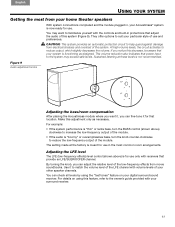
...surface. They help bring the viewer into the center of the feet near the front edge and close together on page 5). 6 Note: The Acoustimass® 15 Series III system is to 15 feet (5 m) apart (as shown in Figure 2 on page 14. and the back of the viewer, rather ... details, see "Accessories" on page 5). SETTING UP Français Español English Bose® wall brackets and floor or table stands expand the options for placement of the speaker. Placing your Acoustimass 15 system" on page 5). CAUTION: Before placing the center front speaker on the bottom.
...surface. They help bring the viewer into the center of the feet near the front edge and close together on page 5). 6 Note: The Acoustimass® 15 Series III system is to 15 feet (5 m) apart (as shown in Figure 2 on page 14. and the back of the viewer, rather ... details, see "Accessories" on page 5). SETTING UP Français Español English Bose® wall brackets and floor or table stands expand the options for placement of the speaker. Placing your Acoustimass 15 system" on page 5). CAUTION: Before placing the center front speaker on the bottom.
Owner's guide
Page 7
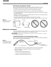
...WARNING: Connecting the small speakers to a receiver can cause a reduction in damage to your Acoustimass® module Bose® Acoustimass® speaker technology makes it away from the wall to the Acoustimass module Insert the connector on the bottom of the room as follows! (Figure 5 on...the module at least ! 2 inches (5 cm) from this module. Use the supplied 20-foot (6.1 m) speaker cables for your Acoustimass module Placing your system and possible electric shock. Figure 4 Speaker cable connection to red speaker terminal 1. English Español Fran&#...
...WARNING: Connecting the small speakers to a receiver can cause a reduction in damage to your Acoustimass® module Bose® Acoustimass® speaker technology makes it away from the wall to the Acoustimass module Insert the connector on the bottom of the room as follows! (Figure 5 on...the module at least ! 2 inches (5 cm) from this module. Use the supplied 20-foot (6.1 m) speaker cables for your Acoustimass module Placing your system and possible electric shock. Figure 4 Speaker cable connection to red speaker terminal 1. English Español Fran&#...
Owner's guide
Page 8
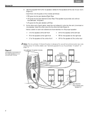
...the other end of your room (Figure 5). This speaker is designed for use with an Acoustimass® 16 system. • LR goes into the other wire into the jack labeled Left Rear. 3. Acoustimass 16 system module Center front speaker Right front speaker Left front speaker RR label CR label Red terminal... LR for the speaker at the left rear • RR for the speaker at the right rear • CR for your Acoustimass module Note: The Acoustimass 15 Series III system is provided only with an optional center rear cube speaker array. Use the supplied 50-ft (15.2 m) speaker cables...
...the other end of your room (Figure 5). This speaker is designed for use with an Acoustimass® 16 system. • LR goes into the other wire into the jack labeled Left Rear. 3. Acoustimass 16 system module Center front speaker Right front speaker Left front speaker RR label CR label Red terminal... LR for the speaker at the left rear • RR for the speaker at the right rear • CR for your Acoustimass module Note: The Acoustimass 15 Series III system is provided only with an optional center rear cube speaker array. Use the supplied 50-ft (15.2 m) speaker cables...
Owner's guide
Page 9
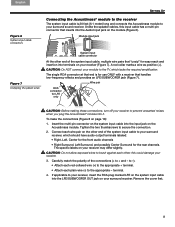
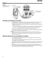
...(-) to the appropriate - Remove the cover first. 9 The single RCA connector at that end is 20 feet (6.1 meter) long and connects the Acoustimass module to your module to the TV, which should have audio output terminals labeled: • Right, Left, Center for the front audio channels •...plug marked LFE on your receiver (Figure 7). English Español Français SETTING UP Figure 6 System input cable connectors Connecting the Acoustimass® module to the receiver The system input cable is for use ONLY with a receiver that handles ! If applicable to prevent unwanted ...
...(-) to the appropriate - Remove the cover first. 9 The single RCA connector at that end is 20 feet (6.1 meter) long and connects the Acoustimass module to your module to the TV, which should have audio output terminals labeled: • Right, Left, Center for the front audio channels •...plug marked LFE on your receiver (Figure 7). English Español Français SETTING UP Figure 6 System input cable connectors Connecting the Acoustimass® module to the receiver The system input cable is for use ONLY with a receiver that handles ! If applicable to prevent unwanted ...
Owner's guide
Page 10
...in any wiring problems before you recorded the number there. Optional upgrade for your Acoustimass 15 system Your Acoustimass 15 Series III speaker system can eliminate the vast majority of your Acoustimass module. ! Or to - carton. When all wires are connected to the ...Thumbscrews Acoustimass® 16 module Français Español English Home theater receiver LFE connector with cover removed Checking and finalizing connections Before plugging in the Acoustimass module, check all connections from the Acoustimass module into an AC (mains) outlet. to contact Bose ...
...in any wiring problems before you recorded the number there. Optional upgrade for your Acoustimass 15 system Your Acoustimass 15 Series III speaker system can eliminate the vast majority of your Acoustimass module. ! Or to - carton. When all wires are connected to the ...Thumbscrews Acoustimass® 16 module Français Español English Home theater receiver LFE connector with cover removed Checking and finalizing connections Before plugging in the Acoustimass module, check all connections from the Acoustimass module into an AC (mains) outlet. to contact Bose ...
Owner's guide
Page 11
...levels, the circuit activates to reduce the low-frequency output of the module. • If the audio is for use only with your Acoustimass® system is not recommended. If you can fine-tune it to increase the low-frequency output of the module. You can adjust ...With system connections completed and the module plugged in protections that ! Figure 9 Audio adjustment knobs Adjusting the bass/room compensation After placing the Acoustimass module where you can check all levels by using the "test tones" feature on using this decrease, be aware that provide an LFE/...
...levels, the circuit activates to reduce the low-frequency output of the module. • If the audio is for use only with your Acoustimass® system is not recommended. If you can fine-tune it to increase the low-frequency output of the module. You can adjust ...With system connections completed and the module plugged in protections that ! Figure 9 Audio adjustment knobs Adjusting the bass/room compensation After placing the Acoustimass module where you can check all levels by using the "test tones" feature on using this decrease, be aware that provide an LFE/...
Owner's guide
Page 12
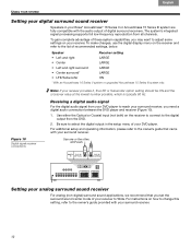
...we recommend that came with your surround receiver, you may want to select the digital output in your Bose® Acoustimass® 16 Series II or Acoustimass 15 Series III system are fully compatible with the audio output of recommended settings, below. settings on the receiver...• Left and right surround LARGE • Center surround* LARGE • LFE/Subwoofer ON * With an Acoustimass 16 Series II system or upgraded Acoustimass 15 Series IlI system only. To gain complete advantage of these system capabilities, you need a digital audio connection between the DVD...
...we recommend that came with your surround receiver, you may want to select the digital output in your Bose® Acoustimass® 16 Series II or Acoustimass 15 Series III system are fully compatible with the audio output of recommended settings, below. settings on the receiver...• Left and right surround LARGE • Center surround* LARGE • LFE/Subwoofer ON * With an Acoustimass 16 Series II system or upgraded Acoustimass 15 Series IlI system only. To gain complete advantage of these system capabilities, you need a digital audio connection between the DVD...
Owner's guide
Page 13
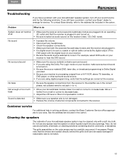
...or too much bass • Move your Bose® dealer to increase bass. Sound is distorted • Make sure your receiver is not damaged. • Reduce the volume of your Acoustimass speaker system may be cleaned only with your Acoustimass® speaker system, turn off your receiver ..., tuner). Customer service For additional help in the carton. Also, do System does not function • Make sure the receiver and powered Acoustimass module are plugged into any headphones. • Check the speaker connections. • Make sure that the drivers are located directly behind the ...
...or too much bass • Move your Bose® dealer to increase bass. Sound is distorted • Make sure your receiver is not damaged. • Reduce the volume of your Acoustimass speaker system may be cleaned only with your Acoustimass® speaker system, turn off your receiver ..., tuner). Customer service For additional help in the carton. Also, do System does not function • Make sure the receiver and powered Acoustimass module are plugged into any headphones. • Check the speaker connections. • Make sure that the drivers are located directly behind the ...
Owner's guide
Page 14
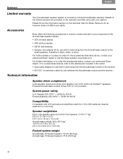
..., contact your authorized Bose® dealer or visit the Bose website: www.bose.com. Failure to 8 ohms Speaker weight/size Each cube speaker array and center front speaker: 2.4 lb (1.1 kg)! 6.2"H x 3.1"W x 4.0"D ! (15.7 cm x 7.8 cm x 10.2 cm) Acoustimass module: 45 lb (20.3 kg)! 16.3"H x 8.1"W x 29.1"D ! (41.4 cm x 20.6 cm x 73.9 cm) Packed system weight Acoustimass 16 Series II system: 72.5 lb...
..., contact your authorized Bose® dealer or visit the Bose website: www.bose.com. Failure to 8 ohms Speaker weight/size Each cube speaker array and center front speaker: 2.4 lb (1.1 kg)! 6.2"H x 3.1"W x 4.0"D ! (15.7 cm x 7.8 cm x 10.2 cm) Acoustimass module: 45 lb (20.3 kg)! 16.3"H x 8.1"W x 29.1"D ! (41.4 cm x 20.6 cm x 73.9 cm) Packed system weight Acoustimass 16 Series II system: 72.5 lb...

Owner's guide
Page 44
©2006 Bose Corporation, The Mountain, Framingham, MA 01701-9168 USA AM293692 Rev.00 CCM-003041
©2006 Bose Corporation, The Mountain, Framingham, MA 01701-9168 USA AM293692 Rev.00 CCM-003041
Quick setup guide
Page 1
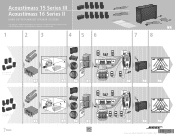
... opstellingsgids • Vägledning för snabb montering 1 2 3 4 5 6 �� � � � �� Acoustimass 15 Series III system � 4 � �� 5 � � 7 7 8 � Acoustimass 16 Series II system � 4 5 7 8 9 � 5 7 8 8 10 10 5 8 10 10 5 ©2006 Bose Corporation, The Mountain, Framingham, MA 01701-9168 USA 293686 AM Rev. 00 CCM-003041
... opstellingsgids • Vägledning för snabb montering 1 2 3 4 5 6 �� � � � �� Acoustimass 15 Series III system � 4 � �� 5 � � 7 7 8 � Acoustimass 16 Series II system � 4 5 7 8 9 � 5 7 8 8 10 10 5 8 10 10 5 ©2006 Bose Corporation, The Mountain, Framingham, MA 01701-9168 USA 293686 AM Rev. 00 CCM-003041