
Installation Instructions
Page 3
... of Electric Fans • ANSI Z21.1, The American National Standard for the Safety of the appliance. Install anti-tip device packaged with range. Destroy the packaging after unpacking the appliance. Improper installation, service or maintenance can tip. Verify that the anti-tip devices are a ...maximum of the cabinet. • Verify that projects horizontally a minimum of 5 inches beyond the bottom of 13" (330 mm) deep. • Do not lift appliance by door handle. For example, do not remove leveling legs,...
... of Electric Fans • ANSI Z21.1, The American National Standard for the Safety of the appliance. Install anti-tip device packaged with range. Destroy the packaging after unpacking the appliance. Improper installation, service or maintenance can tip. Verify that the anti-tip devices are a ...maximum of the cabinet. • Verify that projects horizontally a minimum of 5 inches beyond the bottom of 13" (330 mm) deep. • Do not lift appliance by door handle. For example, do not remove leveling legs,...
Installation Instructions
Page 4
...the wall receptacle is properly installed and grounded by a qualified tech- English 2 Save these instructions for the local electrical inspector's use with ranges" shall be used. • Installer - Installation, electrical connections and grounding must be plugged into a matching grounding type receptacle to avoid ...apply to specific installations. • Installation must conform with local codes or, in the absence of local codes, with the National Fuel Gas Code, ANSI Z223.1/NFPA 54. • The appliance must be electrically grounded in accordance with local codes or, in the...
...the wall receptacle is properly installed and grounded by a qualified tech- English 2 Save these instructions for the local electrical inspector's use with ranges" shall be used. • Installer - Installation, electrical connections and grounding must be plugged into a matching grounding type receptacle to avoid ...apply to specific installations. • Installation must conform with local codes or, in the absence of local codes, with the National Fuel Gas Code, ANSI Z223.1/NFPA 54. • The appliance must be electrically grounded in accordance with local codes or, in the...
Installation Instructions
Page 6
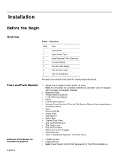
... installations; to the sections that follow for Gas Leaks 7. Connect Electric 5. Tools and Parts Needed Additional Parts Needed For Hard Wire Installations • Range Power Supply Cord Kit (240V -30 Amp) Note: Not necessary for Anti-Tip Bracket (Style will vary depending on mounting surface) • Level • Drill and Drill Bit...
... installations; to the sections that follow for Gas Leaks 7. Connect Electric 5. Tools and Parts Needed Additional Parts Needed For Hard Wire Installations • Range Power Supply Cord Kit (240V -30 Amp) Note: Not necessary for Anti-Tip Bracket (Style will vary depending on mounting surface) • Level • Drill and Drill Bit...
Installation Instructions
Page 7
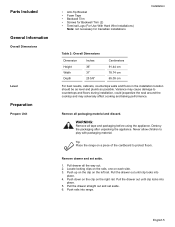
...Remove all packaging material and discard. Pull the drawer out until clip locks into place. 5. Pull the drawer out until clip locks into range. Pull the drawer straight out and set aside. 1. English 5 Parts Included General Information Overall Dimensions Level Preparation Prepare Unit • Anti... Lugs (For Use With Hard Wire Installations) Note: not necessary for Canadian installations Installation Table 2: Overall Dimensions Dimension Height Width Depth Inches 36" 31" 25 5/8" Centimeters 91.44 cm 78.74 cm 65.09 cm For best results, cabinets, countertops walls and floors...
...Remove all packaging material and discard. Pull the drawer out until clip locks into place. 5. Pull the drawer out until clip locks into range. Pull the drawer straight out and set aside. 1. English 5 Parts Included General Information Overall Dimensions Level Preparation Prepare Unit • Anti... Lugs (For Use With Hard Wire Installations) Note: not necessary for Canadian installations Installation Table 2: Overall Dimensions Dimension Height Width Depth Inches 36" 31" 25 5/8" Centimeters 91.44 cm 78.74 cm 65.09 cm For best results, cabinets, countertops walls and floors...
Installation Instructions
Page 8
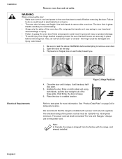
... securely in place before removing door. Also, do so could result in personal injury or product damage. • To avoid injury from the factory with Ranges." Place the door in your hand and cause damage or injury. • Failure to remove oven door. 2. Handle carefully to avoid breaking. • ...the way. 3. English 6 The door front is heavy. 6. The power cord set aside. Installation Remove oven door and set shall be 120/240 volt, 30 amperes minimum. WARNING: When removing the door: • Make sure oven is shipped from hinge bracket snapping closed -
... securely in place before removing door. Also, do so could result in personal injury or product damage. • To avoid injury from the factory with Ranges." Place the door in your hand and cause damage or injury. • Failure to remove oven door. 2. Handle carefully to avoid breaking. • ...the way. 3. English 6 The door front is heavy. 6. The power cord set aside. Installation Remove oven door and set shall be 120/240 volt, 30 amperes minimum. WARNING: When removing the door: • Make sure oven is shipped from hinge bracket snapping closed -
Installation Instructions
Page 9
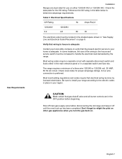
... a minimum of the wiring to the house and service switch must be done by the range. Check local codes for the kW rating. CAUTION: Make certain that gas shutoff valve and all burner controls are dual rated for use on . In some instances, the size of a three wire 120/240 ... VAC or 120/208 VAC. A four wire connection is adequate. Table 3: Electrical Specifications kW Rating Hz Amps Req'd 120/240V 6.2 120/208V 4.8 60 30 The electrical outlet must be increased to verify that electrical wiring be located in the shaded space shown in "Gas Supply Line and Electrical Outlet...
... a minimum of the wiring to the house and service switch must be done by the range. Check local codes for the kW rating. CAUTION: Make certain that gas shutoff valve and all burner controls are dual rated for use on . In some instances, the size of a three wire 120/240 ... VAC or 120/208 VAC. A four wire connection is adequate. Table 3: Electrical Specifications kW Rating Hz Amps Req'd 120/240V 6.2 120/208V 4.8 60 30 The electrical outlet must be increased to verify that electrical wiring be located in the shaded space shown in "Gas Supply Line and Electrical Outlet...

Installation Instructions
Page 10
... to the range. Prepare the countertop and cabinets as shown in Figure 4: Gas Supply Line and Electrical Outlet Placement. 7 1/2" (190.5 mm) 3 1/2" 88.9 mm 4 1/2" 114.3 mm 4" (101.6 mm) 13 1/8 " (333 mm) 3 7/8" (98 mm) 30" (762 mm) 4 1/2" 114.3 mm Figure 4: Gas Supply Line and ...gas, your range must be installed. 23 1/16" (585.4 mm) English 8 30" (762 mm) Figure 5: Cutout Requirements - Typical Installation. Make sure all users know where and how to shut off valve in Figure 5: Cutout Requirements - Allow a minimum of 30 inches between cabinets where range is shipped from...
... to the range. Prepare the countertop and cabinets as shown in Figure 4: Gas Supply Line and Electrical Outlet Placement. 7 1/2" (190.5 mm) 3 1/2" 88.9 mm 4 1/2" 114.3 mm 4" (101.6 mm) 13 1/8 " (333 mm) 3 7/8" (98 mm) 30" (762 mm) 4 1/2" 114.3 mm Figure 4: Gas Supply Line and ...gas, your range must be installed. 23 1/16" (585.4 mm) English 8 30" (762 mm) Figure 5: Cutout Requirements - Typical Installation. Make sure all users know where and how to shut off valve in Figure 5: Cutout Requirements - Allow a minimum of 30 inches between cabinets where range is shipped from...
Installation Instructions
Page 11
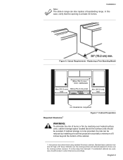
...can also replace a freestanding range. centered 4in (10.2 cm ) 30in (76.2 cm) min. 4in (10.2 cm) min min no clearance required Required Clearance1 Figure 7: Cabinet Preparation WARNING: To eliminate the risk of the cabinet. 1. If cabinet storage is at least 30 inches. In this case, verify... that projects horizontally a minimum of 5 inches beyond the bottom of burns or fire by installing a hood that the opening is to alter dimensions ...
...can also replace a freestanding range. centered 4in (10.2 cm ) 30in (76.2 cm) min. 4in (10.2 cm) min min no clearance required Required Clearance1 Figure 7: Cabinet Preparation WARNING: To eliminate the risk of the cabinet. 1. If cabinet storage is at least 30 inches. In this case, verify... that projects horizontally a minimum of 5 inches beyond the bottom of burns or fire by installing a hood that the opening is to alter dimensions ...

Installation Instructions
Page 12
... retardant material which must be a minimum clearance of 30 inches between the top of the cooking surface and the bottom of not less than 300 CFM is protected by safety standards, particularly self-cleaning ovens; Measure to adjacent materials: See Figure 7: Cabinet Preparation. The range hood must be installed according to adjacent vertical...
... retardant material which must be a minimum clearance of 30 inches between the top of the cooking surface and the bottom of not less than 300 CFM is protected by safety standards, particularly self-cleaning ovens; Measure to adjacent materials: See Figure 7: Cabinet Preparation. The range hood must be installed according to adjacent vertical...
Installation Instructions
Page 13
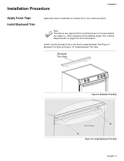
... continuous piece. Note: This step is only required if the countertop does not connect behind the range (i.e.; when replacing a free-standing range). Installation Procedure Installation Apply Foam Tape Install Backwall Trim Apply foam tape to underside of Range Figure 10: Install Backwall Trim Strip English 11 See Figure 9: Backwall Trim Strip and Figure...
... continuous piece. Note: This step is only required if the countertop does not connect behind the range (i.e.; when replacing a free-standing range). Installation Procedure Installation Apply Foam Tape Install Backwall Trim Apply foam tape to underside of Range Figure 10: Install Backwall Trim Strip English 11 See Figure 9: Backwall Trim Strip and Figure...
Installation Instructions
Page 14
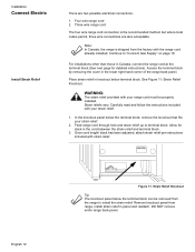
...panel from the factory with your strain relief. 1. Place strain relief in the cord between the strain relief and terminal block. 3. Feed range cord through hole and strain relief up to "Connect Gas Supply" on page 16. Installation Connect Electric Install Strain Relief There are also... acceptable. Note: In Canada, the range is the recommended method, but where local codes permit, three wire connections are two possible electrical connections: 1. Access the terminal block by...
...panel from the factory with your strain relief. 1. Place strain relief in the cord between the strain relief and terminal block. 3. Feed range cord through hole and strain relief up to "Connect Gas Supply" on page 16. Installation Connect Electric Install Strain Relief There are also... acceptable. Note: In Canada, the range is the recommended method, but where local codes permit, three wire connections are two possible electrical connections: 1. Access the terminal block by...
Installation Instructions
Page 15
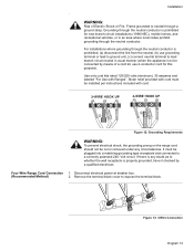
... ground strap. Volt circuit. It must be cut or removed under any doubt as to neutral through the neutral conductor. Four Wire Range Cord Connection 1. Remove the terminal block cover to a correctly polarized 240- Frame grounded to whether the wall receptacle is properly grounded, ... provided with Ranges". WARNING: Risk of a cord kit, use grounding terminal or lead to ground unit, (c) connect neutral terminal to be plugged into a matching grounding type receptacle and connected to expose the terminal block. Use only cord kits rated 125/250 volts (minimum), 30 amperes and...
... ground strap. Volt circuit. It must be cut or removed under any doubt as to neutral through the neutral conductor. Four Wire Range Cord Connection 1. Remove the terminal block cover to a correctly polarized 240- Frame grounded to whether the wall receptacle is properly grounded, ... provided with Ranges". WARNING: Risk of a cord kit, use grounding terminal or lead to ground unit, (c) connect neutral terminal to be plugged into a matching grounding type receptacle and connected to expose the terminal block. Use only cord kits rated 125/250 volts (minimum), 30 amperes and...

Installation Instructions
Page 16
.... 10. Remove ground strap from bottom end of ground strap. English 14 black red white Figure 15: Four Wire Range Cord Connection (continued) 9. Note: DO NOT plug in range at top and attach wide end to right post. Tighten Screw. Attach black wire, round washer, star washer and ... hole below junction box. Properly secure strain relief (see previous section). green ground screw ground strap ground wire Figure 14: Four Wire Range Cord Connection - Note: DO NOT remove last round washer, last nut or internal wiring leads. 4. Ground Strap and Wire 6. Attach green wire...
.... 10. Remove ground strap from bottom end of ground strap. English 14 black red white Figure 15: Four Wire Range Cord Connection (continued) 9. Note: DO NOT plug in range at top and attach wide end to right post. Tighten Screw. Attach black wire, round washer, star washer and ... hole below junction box. Properly secure strain relief (see previous section). green ground screw ground strap ground wire Figure 14: Four Wire Range Cord Connection - Note: DO NOT remove last round washer, last nut or internal wiring leads. 4. Ground Strap and Wire 6. Attach green wire...

Installation Instructions
Page 17
... THIS ORDER to the power supply via a three wire connection. 1. ground strap white red black Figure 17: Three Wire Connection English 15 Installation Three Wire Range Cord Connection The Four Wire Connection (above) is preferred, but where local codes and ordinances permit grounding through neutral and where conversion to four wire...
... THIS ORDER to the power supply via a three wire connection. 1. ground strap white red black Figure 17: Three Wire Connection English 15 Installation Three Wire Range Cord Connection The Four Wire Connection (above) is preferred, but where local codes and ordinances permit grounding through neutral and where conversion to four wire...
Installation Instructions
Page 18
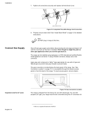
...using the LP conversion kit. See "Install Strain Relief" on page 12 for LP users Figure 19: Gas Connection Location The range is a registered trademark of the range. The gas connection is accessible through the drawer access panel or from the factory for use with natural gas. green ground ...Properly secure strain relief. Connect Gas Supply Shut off main gas supply valve before disconnecting the old range and leave it off until the new hook-up has been completed. The range can be converted using a flexible connector, always use with LP gas and Natural gas around all ...
...using the LP conversion kit. See "Install Strain Relief" on page 12 for LP users Figure 19: Gas Connection Location The range is a registered trademark of the range. The gas connection is accessible through the drawer access panel or from the factory for use with natural gas. green ground ...Properly secure strain relief. Connect Gas Supply Shut off main gas supply valve before disconnecting the old range and leave it off until the new hook-up has been completed. The range can be converted using a flexible connector, always use with LP gas and Natural gas around all ...
Installation Instructions
Page 19
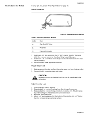
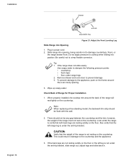
... . 2. Install male 1/2" or 3/4" flare union adapter on the internal thread of the range inlet. CAUTION: Before you plug in an electrical cord, be sure all controls are in Range Cord 1. Adjust Leveling Legs 1. Adjust leveling leg until this height is off and then plug...Flexible Connector Method Letter Item A Gas Shut Off Valve B Regulator C Flexible Connector Figure 20: Flexible Connector Method 1. Measure back left corner of range to bottom of opening from floor to avoid damage. 2. English 17 Repeat in front of cooktop trim. Connect flexible connector at the 1/2" NPT ...
... . 2. Install male 1/2" or 3/4" flare union adapter on the internal thread of the range inlet. CAUTION: Before you plug in an electrical cord, be sure all controls are in Range Cord 1. Adjust Leveling Legs 1. Adjust leveling leg until this height is off and then plug...Flexible Connector Method Letter Item A Gas Shut Off Valve B Regulator C Flexible Connector Figure 20: Flexible Connector Method 1. Measure back left corner of range to bottom of opening from floor to avoid damage. 2. English 17 Repeat in front of cooktop trim. Connect flexible connector at the 1/2" NPT ...
Installation Instructions
Page 20
...prevent damage 3. When properly installed, the cooktop trim around the oven cavity opening , being careful not to damage countertops, floors, or the range drawer front. This could result in power cord. 2. If the back legs are resting solidly on the countertop. Do not apply pressure to ... into opening . 3. Remove drawer and oven door to crimp flexible connector. Look under the anti-tip bracket, slide range out, adjust legs and slide back in. Slide range into position. Wipe up soapy water. Note: When replacing a free-standing model, the backwall trim strip should not ...
...prevent damage 3. When properly installed, the cooktop trim around the oven cavity opening , being careful not to damage countertops, floors, or the range drawer front. This could result in power cord. 2. If the back legs are resting solidly on the countertop. Do not apply pressure to ... into opening . 3. Remove drawer and oven door to crimp flexible connector. Look under the anti-tip bracket, slide range out, adjust legs and slide back in. Slide range into position. Wipe up soapy water. Note: When replacing a free-standing model, the backwall trim strip should not ...

Installation Instructions
Page 21
Rigid Pipe Method Adjust Front of the gas pipe stub. vents tip-over. If using a flexible connector, return to Range F Table 5: Rigid Pipe Method Letter A B C D Item Elbow; Adjust front leveling legs so that both front legs are resting solidly on page 17. The gas connection ... 3/4" Gas Pipe Figure 22: Rigid Pipe Method The configuration of the rigid pipe connection will vary depending on page 21. Proceed to ensure that the range is complete. English 19 See Figure 22: Rigid Pipe Method for Gas Leaks" on the location of...
Rigid Pipe Method Adjust Front of the gas pipe stub. vents tip-over. If using a flexible connector, return to Range F Table 5: Rigid Pipe Method Letter A B C D Item Elbow; Adjust front leveling legs so that both front legs are resting solidly on page 17. The gas connection ... 3/4" Gas Pipe Figure 22: Rigid Pipe Method The configuration of the rigid pipe connection will vary depending on page 21. Proceed to ensure that the range is complete. English 19 See Figure 22: Rigid Pipe Method for Gas Leaks" on the location of...
Installation Instructions
Page 22
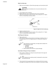
...door to dampen the following pressure points: • countertop • foam tape • floor under the range When properly installed, the cooktop trim around the back of Range for Proper Installation 1. however, the weight of the cooktop trim is ½" higher than the corresponding countertop... surface. Installation English 20 Adjust Leveling Legs 1. Adjust front leveling legs so that the bottom of the range must not rest on the countertop. Note: When replacing a free-standing model, the backwall trim strip should not be flush with the...
...door to dampen the following pressure points: • countertop • foam tape • floor under the range When properly installed, the cooktop trim around the back of Range for Proper Installation 1. however, the weight of the cooktop trim is ½" higher than the corresponding countertop... surface. Installation English 20 Adjust Leveling Legs 1. Adjust front leveling legs so that the bottom of the range must not rest on the countertop. Note: When replacing a free-standing model, the backwall trim strip should not be flush with the...

Installation Instructions
Page 23
... indicate a leak. 4. Leak testing is to be conducted by the installer according to the instructions given in damage to verify that the range is not under the anti-tip bracket. Include all detection fluid residue. CAUTION: Never check for Gas Leaks Installation to the countertop and ...the appliance. 3. vents tip-over. Test for leaks with a flame. Push range back into position ensuring that the left leg is level and plumb. 4. Note: Be careful not to apply pressure to "Test for leaks. CAUTION...
... indicate a leak. 4. Leak testing is to be conducted by the installer according to the instructions given in damage to verify that the range is not under the anti-tip bracket. Include all detection fluid residue. CAUTION: Never check for Gas Leaks Installation to the countertop and ...the appliance. 3. vents tip-over. Test for leaks with a flame. Push range back into position ensuring that the left leg is level and plumb. 4. Note: Be careful not to apply pressure to "Test for leaks. CAUTION...


