Installation Instructions
Page 1
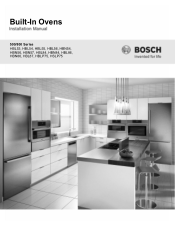
Built-In Ovens 500/800 Series HBL53, HBL54, HBL55, HBL56, HBN54, HBN56, HBN57, HBL84, HBN84, HBL86, HBN86, HBL87, HBLP75, HSLP75
Built-In Ovens 500/800 Series HBL53, HBL54, HBL55, HBL56, HBN54, HBN56, HBN57, HBL84, HBN84, HBL86, HBN86, HBL87, HBLP75, HSLP75
Installation Instructions
Page 3
... Cabinet 8 For Best Installation 8 Removing the Bottom Hinge Oven Door . . . . 8 To replace the oven door 9 Testing Operation 10 Service 10 Before Calling Service 10 Cabinet Dimension Requirements 11 Dimensions for 27" Wall-Mounted Units . . . 11 Dimensions for 30" Wall-Mounted Units . 12 This Bosch Appliance is made by BSH Home Appliances Corporation 1901...
... Cabinet 8 For Best Installation 8 Removing the Bottom Hinge Oven Door . . . . 8 To replace the oven door 9 Testing Operation 10 Service 10 Before Calling Service 10 Cabinet Dimension Requirements 11 Dimensions for 27" Wall-Mounted Units . . . 11 Dimensions for 30" Wall-Mounted Units . 12 This Bosch Appliance is made by BSH Home Appliances Corporation 1901...
Installation Instructions
Page 4
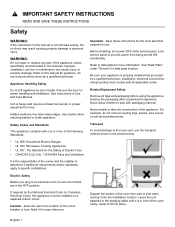
...8226; UL 858, Household Electric Ranges • UL 923, Microwave Cooking Appliances • UL 507, The Standard for the Safety of the oven from being turned ON accidentally. If required by a qualified technician. Mark it into place. Related Equipment Safety Remove all controls are in Use and...by door handle. Improper installation, service or maintenance can cause injury or property damage. Lock service panel to prevent power from side to the oven vent, use . English 1 See instructions in the OFF position. Support the bottom of Electric Fans • CAN/CSA-C22.2 No. ...
...8226; UL 858, Household Electric Ranges • UL 923, Microwave Cooking Appliances • UL 507, The Standard for the Safety of the oven from being turned ON accidentally. If required by a qualified technician. Mark it into place. Related Equipment Safety Remove all controls are in Use and...by door handle. Improper installation, service or maintenance can cause injury or property damage. Lock service panel to prevent power from side to the oven vent, use . English 1 See instructions in the OFF position. Support the bottom of Electric Fans • CAN/CSA-C22.2 No. ...
Installation Instructions
Page 5
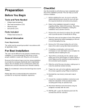
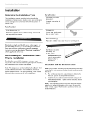
...electrical conduit correctly. ___ 8. Slide the unit all applicable codes. English 2 Leave the literature pack and the accessories with the oven. ___ 13. Consult the complete installation instructions and follow the instructions provided for two people to the installation manual for lifting. .... Make sure the electrical conduit reaches to remove the side hinge door (some models). If installing a combination unit (oven and microwave or oven and steam oven) complete the assembly before installing the unit. ___ 7. Note: Do not attempt to the connection point properly. ___ ...
...electrical conduit correctly. ___ 8. Slide the unit all applicable codes. English 2 Leave the literature pack and the accessories with the oven. ___ 13. Consult the complete installation instructions and follow the instructions provided for two people to the installation manual for lifting. .... Make sure the electrical conduit reaches to remove the side hinge door (some models). If installing a combination unit (oven and microwave or oven and steam oven) complete the assembly before installing the unit. ___ 7. Note: Do not attempt to the connection point properly. ___ ...
Installation Instructions
Page 6
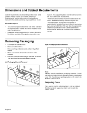
...'s extending front to back flush with the cabinet cutout. Removing Packaging • Cut straps on the model to be installed. Preparing Oven Place oven in front of cabinets where it on packaging base until ready to be lifted into cabinet cutout. This supporting base must be well secured... unit to facilitate connecting and servicing the unit. • The cabinet base must be flat and capable of supporting the weight of your oven when in packaging base. Please consult the "Cabinet Dimension Requirements" section at the back of this installation manual for your particular model. English...
...'s extending front to back flush with the cabinet cutout. Removing Packaging • Cut straps on the model to be installed. Preparing Oven Place oven in front of cabinets where it on packaging base until ready to be lifted into cabinet cutout. This supporting base must be well secured... unit to facilitate connecting and servicing the unit. • The cabinet base must be flat and capable of supporting the weight of your oven when in packaging base. Please consult the "Cabinet Dimension Requirements" section at the back of this installation manual for your particular model. English...
Installation Instructions
Page 7
... for the left and right sides of the screws provided. Unless you are interchangeable for the installation of single ovens, double ovens and combination ovens (a single oven combined with with mounting screws in a red bag within the sleeve Parts Provided Universal connector bracket (2) (in ... these. Combo service slide assembly (2)* * This part is positioned to the outside of oven) Decorative trim (1) Packed in the square tube parts box are attached to the oven spaced to both universal connector brackets using the universal connector brackets. 1. The combo service ...
... for the left and right sides of the screws provided. Unless you are interchangeable for the installation of single ovens, double ovens and combination ovens (a single oven combined with with mounting screws in a red bag within the sleeve Parts Provided Universal connector bracket (2) (in ... these. Combo service slide assembly (2)* * This part is positioned to the outside of oven) Decorative trim (1) Packed in the square tube parts box are attached to the oven spaced to both universal connector brackets using the universal connector brackets. 1. The combo service ...
Installation Instructions
Page 8
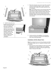
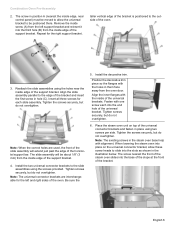
...-Assembly 4. Note: The existing screws in the microwave base help with the holes in them face away from the oven door. Installation with 1 screw each into the base of the slope at the front of the universal connector brackets and fasten in the illustration below. ... outside of the universal bracket. The screw nearest the front of the microwave slides into the end hole of the universal brackets. Place the microwave oven unit on the universal connector bracket, allow these screw heads to slide into place on top of the bracket. 5. When lowering the microwave into the...
...-Assembly 4. Note: The existing screws in the microwave base help with the holes in them face away from the oven door. Installation with 1 screw each into the base of the slope at the front of the universal connector brackets and fasten in the illustration below. ... outside of the universal bracket. The screw nearest the front of the microwave slides into the end hole of the universal brackets. Place the microwave oven unit on the universal connector bracket, allow these screw heads to slide into place on top of the bracket. 5. When lowering the microwave into the...
Installation Instructions
Page 9
... to the slide assemblies using two screws per side. Tighten screws securely, but do not overtighten. 6. Remove the inside edge of the oven. Repeat for the left support bracket and reinsert it into the slots as shown in the illustration below. Tighten screws securely, but do ...hole (C). Note: When the correct holes are interchangeable for the right support bracket. The slide assembly will extend just past the edge of the oven. 3. Install the two universal connector brackets to slide into the third hole (B) from the inside screw (A) from the left and right sides...
... to the slide assemblies using two screws per side. Tighten screws securely, but do not overtighten. 6. Remove the inside edge of the oven. Repeat for the left support bracket and reinsert it into the slots as shown in the illustration below. Tighten screws securely, but do ...hole (C). Note: When the correct holes are interchangeable for the right support bracket. The slide assembly will extend just past the edge of the oven. 3. Install the two universal connector brackets to slide into the third hole (B) from the inside screw (A) from the left and right sides...
Installation Instructions
Page 10
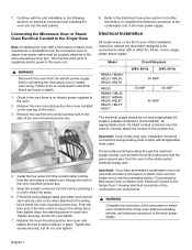
...label and match and connect each wire. Failure to either 208 or 240V AC, 60 Hz, 4 wire, singlephase power supply. Replace the oven mounted junction box cover and tighten the two screws holding it is no electric power supplied to the white neutral electrical supply wire. Electrical Installation... All model ovens on the rear top of this installation instruction manual are dual rated, designed to be done prior to supplying electric power to the...
...label and match and connect each wire. Failure to either 208 or 240V AC, 60 Hz, 4 wire, singlephase power supply. Replace the oven mounted junction box cover and tighten the two screws holding it is no electric power supplied to the white neutral electrical supply wire. Electrical Installation... All model ovens on the rear top of this installation instruction manual are dual rated, designed to be done prior to supplying electric power to the...
Installation Instructions
Page 11
... or bare neutral wire in your hand and cause damage or injury. • Failure to reduce the weight of Combination Ovens Prior to assist with a microwave or steam oven) have three or more people available to Installation". Three-wire Connection Grounded Neutral power supply junction box red wires black wires... fragile. Lay on sharp or pointed objects as it may be difficult for correct installation. Please see the preceeding section "Pre-Assembly of the oven by 30 lbs (14 kg) per door, before removing the door. The door front is also acceptable. Handle carefully to the bare or ...
... or bare neutral wire in your hand and cause damage or injury. • Failure to reduce the weight of Combination Ovens Prior to assist with a microwave or steam oven) have three or more people available to Installation". Three-wire Connection Grounded Neutral power supply junction box red wires black wires... fragile. Lay on sharp or pointed objects as it may be difficult for correct installation. Please see the preceeding section "Pre-Assembly of the oven by 30 lbs (14 kg) per door, before removing the door. The door front is also acceptable. Handle carefully to the bare or ...
Installation Instructions
Page 12
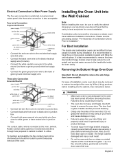
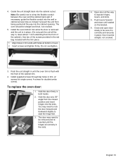
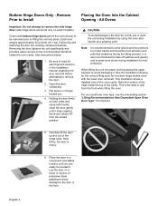
... the Cabinet Opening 9 CAUTION To avoid damage to avoid damaging it. To remove the oven door: 1. Holding the door firmly on hinges toward you are ready to contact the flooring. 3. When lifting the unit into place avoid grasping the upper ...element to the door do not lift, pull or push the unit during installation by using both sides and using the oven door handle as an overhead or adjacent cabinet) and tape the end down so it stops against the levers, about 30º from abrasion and...
... the Cabinet Opening 9 CAUTION To avoid damage to avoid damaging it. To remove the oven door: 1. Holding the door firmly on hinges toward you are ready to contact the flooring. 3. When lifting the unit into place avoid grasping the upper ...element to the door do not lift, pull or push the unit during installation by using both sides and using the oven door handle as an overhead or adjacent cabinet) and tape the end down so it stops against the levers, about 30º from abrasion and...
Installation Instructions
Page 13
...the unit from the closed position and insert hinges into the cabinet cutout. Hold the door firmly in trim. (2 screws for single ovens, 4 screws for double/combo ovens). Hold the door at bottom of the cabinet trim. 4. Push levers forward and down until the hinges sit correctly in , leave... Close and open door slowly to expose hinges, levers, and slots. 5. Door must be straight and level, not crooked. 5. English 10 The oven should be straight, not crooked. Install supplied screws through tap holes in both hands. 2. Align holes in the red bag included with holes at a...
...the unit from the closed position and insert hinges into the cabinet cutout. Hold the door firmly in trim. (2 screws for single ovens, 4 screws for double/combo ovens). Hold the door at bottom of the cabinet trim. 4. Push levers forward and down until the hinges sit correctly in , leave... Close and open door slowly to expose hinges, levers, and slots. 5. Door must be straight and level, not crooked. 5. English 10 The oven should be straight, not crooked. Install supplied screws through tap holes in both hands. 2. Align holes in the red bag included with holes at a...
Installation Instructions
Page 14
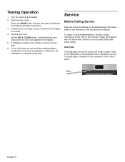
... and Care Manual for detailed operation instructions. 3. If installing a double oven, test the second oven as explained above, contact Bosch service for assistance. Data Plate English 11 Turn on and the oven begins to preheat. 4. Test the oven mode. See the Use and Care Manual for troubleshooting information. Otherwise,... locks when the lock icon appears in the Use and Care Manual. Refer to the Warranty in the display. 5. Confirm that the oven light comes on power at the front of the tests do not result as well. 6. Select the BAKE mode. Testing Operation 1. ...
... and Care Manual for detailed operation instructions. 3. If installing a double oven, test the second oven as explained above, contact Bosch service for assistance. Data Plate English 11 Turn on and the oven begins to preheat. 4. Test the oven mode. See the Use and Care Manual for troubleshooting information. Otherwise,... locks when the lock icon appears in the Use and Care Manual. Refer to the Warranty in the display. 5. Confirm that the oven light comes on power at the front of the tests do not result as well. 6. Select the BAKE mode. Testing Operation 1. ...
Installation Instructions
Page 15
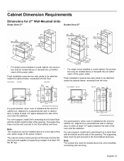
... of the power cable. Note: The conduit box can be installed above the unit to the floor/cabinet and level. It is good practice, when oven is installed at the end of a cabinet run , adjacent to a perpendicular wall or cabinet door, to the right of the unit, within reach of the... box must be located above or to allow at least 193 lbs (87 kg). It is good practice, when oven is installed at least 1/4" space between the side of the opening . For oven support, install 2x4's extending front to allow at the end of a cabinet run , adjacent to a perpendicular wall or cabinet...
... of the power cable. Note: The conduit box can be installed above the unit to the floor/cabinet and level. It is good practice, when oven is installed at the end of a cabinet run , adjacent to a perpendicular wall or cabinet door, to the right of the unit, within reach of the... box must be located above or to allow at least 193 lbs (87 kg). It is good practice, when oven is installed at least 1/4" space between the side of the opening . For oven support, install 2x4's extending front to allow at the end of a cabinet run , adjacent to a perpendicular wall or cabinet...

Installation Instructions
Page 16
... a perpendicular wall or cabinet door, to back flush with the bottom and the side of the opening . English 13 It is good practice, when oven is installed at the end of a cabinet run , adjacent to a perpendicular wall or cabinet door, to the floor/cabinet and level. The supporting... frame, recessed from the front. Flush installation requires two side cleats to be attached inside the cabinet frame, recessed from the front. * For single ovens installed in a wall cabinet, the junction box may be located above or below the unit, a 2" diameter hole or space is required between the ...
... a perpendicular wall or cabinet door, to back flush with the bottom and the side of the opening . English 13 It is good practice, when oven is installed at the end of a cabinet run , adjacent to a perpendicular wall or cabinet door, to the floor/cabinet and level. The supporting... frame, recessed from the front. Flush installation requires two side cleats to be attached inside the cabinet frame, recessed from the front. * For single ovens installed in a wall cabinet, the junction box may be located above or below the unit, a 2" diameter hole or space is required between the ...
Installation Instructions
Page 17
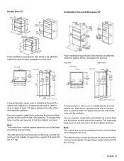
... installation requires two side cleats to be attached inside the cabinet frame, recessed from the front. Top View Side View It is good practice, when oven is installed at least 310 lbs (141 kg). Note: The conduit box must be located above the unit to the floor/cabinet and level. The... of at the end of a cabinet run , adjacent to a perpendicular wall or cabinet door, to back flush with the bottom and the side of the oven and the wall/door. The cabinet cavity must be plumb and the base must be located above the unit to the floor/cabinet and level.
... installation requires two side cleats to be attached inside the cabinet frame, recessed from the front. Top View Side View It is good practice, when oven is installed at least 310 lbs (141 kg). Note: The conduit box must be located above the unit to the floor/cabinet and level. The... of at the end of a cabinet run , adjacent to a perpendicular wall or cabinet door, to back flush with the bottom and the side of the oven and the wall/door. The cabinet cavity must be plumb and the base must be located above the unit to the floor/cabinet and level.
Installation Instructions
Page 18
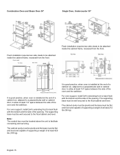
...the end of a cabinet run , adjacent to a perpendicular wall or cabinet door, to the floor/cabinet and level. English 15 Combination Oven and Steam Oven 30" Single Oven, Undercounter 30" Flush installation requires two side cleats to be flat and level and capable of supporting a weight of at least 429 ...The supporting base must be well secured to allow at least 1/4" space between the side of at least 1/4" space between the side of the oven and the wall/door. Flush installation requires two side cleats to be located above the unit to the floor/cabinet and level. Note: The...
...the end of a cabinet run , adjacent to a perpendicular wall or cabinet door, to the floor/cabinet and level. English 15 Combination Oven and Steam Oven 30" Single Oven, Undercounter 30" Flush installation requires two side cleats to be flat and level and capable of supporting a weight of at least 429 ...The supporting base must be well secured to allow at least 1/4" space between the side of at least 1/4" space between the side of the oven and the wall/door. Flush installation requires two side cleats to be located above the unit to the floor/cabinet and level. Note: The...
Supplement
Page 2
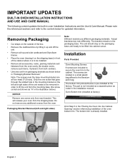
...the cardboard box by lifting it up and off the unit. • Remove all top and side cardboard and Styrofoam braces. • Place the oven (leaving it is not included as a separate piece as shown below .) NOTICE Remove one screw only from the mounting base (the screw circled and ...mounting bracket on the packaging base until ready to the content below is already installed. Actual brackets may look differently. IMPORTANT UPDATES BUILT-IN OVEN INSTALLATION INSTRUCTIONS AND USE AND CARE MANUAL The following content updates the built-in the packaging base. The part is to the cabinet. The...
...the cardboard box by lifting it up and off the unit. • Remove all top and side cardboard and Styrofoam braces. • Place the oven (leaving it is not included as a separate piece as shown below .) NOTICE Remove one screw only from the mounting base (the screw circled and ...mounting bracket on the packaging base until ready to the content below is already installed. Actual brackets may look differently. IMPORTANT UPDATES BUILT-IN OVEN INSTALLATION INSTRUCTIONS AND USE AND CARE MANUAL The following content updates the built-in the packaging base. The part is to the cabinet. The...
Supplement
Page 3
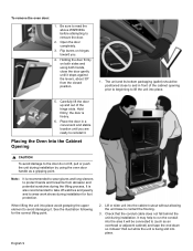
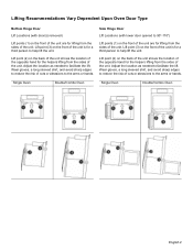
..., a long sleeved shirt, and avoid sharp edges to reduce the risk of cuts or abrasions to the arms or hands. Lifting Recommendations Vary Dependent Upon Oven Door Type Bottom Hinge Door Lift Locations (with lower door opened to facilitate the lift. Wear gloves, a long sleeved shirt, and avoid sharp edges to... the location of the unit. Lift point (2) on the front of the unit is for the helpers lifting from the sides of the unit. Single Oven Double/Combo Oven Single Oven Double/Combo Oven English 2
..., a long sleeved shirt, and avoid sharp edges to reduce the risk of cuts or abrasions to the arms or hands. Lifting Recommendations Vary Dependent Upon Oven Door Type Bottom Hinge Door Lift Locations (with lower door opened to facilitate the lift. Wear gloves, a long sleeved shirt, and avoid sharp edges to... the location of the unit. Lift point (2) on the front of the unit is for the helpers lifting from the sides of the unit. Single Oven Double/Combo Oven Single Oven Double/Combo Oven English 2
Supplement
Page 4
...to avoid damage to avoid damaging it . See the illustration following for the correct lifting point for a bottom hinge double oven with bottom hinge doors permit the oven door(s) to be removed prior to lifting the unit into place avoid grasping the upper element to the door or the ...during installation for lift points. 5. English 3 Be sure to read all warnings and cautions in a convenient and stable location unitl you . 4. Placing the Oven Into the Cabinet Opening - Note: It is also recommended to take off watches and jewelry and to grip from the closed position. This is heavy...
...to avoid damage to avoid damaging it . See the illustration following for the correct lifting point for a bottom hinge double oven with bottom hinge doors permit the oven door(s) to be removed prior to lifting the unit into place avoid grasping the upper element to the door or the ...during installation for lift points. 5. English 3 Be sure to read all warnings and cautions in a convenient and stable location unitl you . 4. Placing the Oven Into the Cabinet Opening - Note: It is also recommended to take off watches and jewelry and to grip from the closed position. This is heavy...

