
Setup Manual
Page 1
... in accordance with the limits of a Class B digital device, pursuant to Part 15 of their respective companies. These limits are trademarks of the FCC Rules. MCP6P3/N68S3 Setup Manual FCC Information and Copyright This equipment has been tested and found in this publication, in part or in whole, is not allowed without...
... in accordance with the limits of a Class B digital device, pursuant to Part 15 of their respective companies. These limits are trademarks of the FCC Rules. MCP6P3/N68S3 Setup Manual FCC Information and Copyright This equipment has been tested and found in this publication, in part or in whole, is not allowed without...
Setup Manual
Page 3
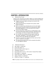
... the edge, do not try to 45 degrees Celsius. 1.2 PACKAGE CHECKLIST IDE Cable X 1(optional) Serial ATA Cable X 2 Rear I/O Panel for choosing our product. CHAPTER 1: INTRODUCTION MCP6P3/N68S3 1.1 BEFORE YOU START Thank you take the motherboard out from anti-static bag, ground yourself properly by touching any unfastened small parts inside ) FDD Cable...
... the edge, do not try to 45 degrees Celsius. 1.2 PACKAGE CHECKLIST IDE Cable X 1(optional) Serial ATA Cable X 2 Rear I/O Panel for choosing our product. CHAPTER 1: INTRODUCTION MCP6P3/N68S3 1.1 BEFORE YOU START Thank you take the motherboard out from anti-static bag, ground yourself properly by touching any unfastened small parts inside ) FDD Cable...
Setup Manual
Page 4
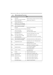
... Transport 2.0 (Maximum Watt: 95W) Support HyperTransport 2.0 FSB Supports up to 2.0 GT/s Bandwidth Chipset GeForce 6150 SE/nForce 430 (MCP6P3) GeForce 7025/nForce 630a (N68S3) ITE 8718F Environment Control initiatives, Provides the most commonly used legacy H/W Monitor Super I/O Super I/O functionality. LAN Realtek RTL 8201CL...Supports DDR3 800 / 1066 / 1333 Registered DIMM and ECC DIMM is not supported Graphics GeForce 6150 SE/nForce 430 (MCP6P3) GeForce 7025/nForce 630a (N68S3) Max Shared Video Memory is 512MB (under OS) IDE Integrated IDE Controller Ultra DMA 33 / 66 / 100 ...
... Transport 2.0 (Maximum Watt: 95W) Support HyperTransport 2.0 FSB Supports up to 2.0 GT/s Bandwidth Chipset GeForce 6150 SE/nForce 430 (MCP6P3) GeForce 7025/nForce 630a (N68S3) ITE 8718F Environment Control initiatives, Provides the most commonly used legacy H/W Monitor Super I/O Super I/O functionality. LAN Realtek RTL 8201CL...Supports DDR3 800 / 1066 / 1333 Registered DIMM and ECC DIMM is not supported Graphics GeForce 6150 SE/nForce 430 (MCP6P3) GeForce 7025/nForce 630a (N68S3) Max Shared Video Memory is 512MB (under OS) IDE Integrated IDE Controller Ultra DMA 33 / 66 / 100 ...
Setup Manual
Page 5
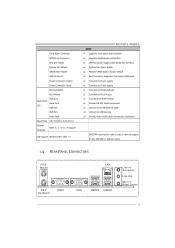
...Serial Port LAN port USB Port Audio Jack Board Size 190 mm(W) x 244 mm(L) Special Features RAID 0 / 1 / 0+1 / 5 support OS Support Windows XP / Vista / 7 MCP6P3/N68S3 SPEC x1 Supports front panel audio function x1 Supports digital audio out function x1 CPU Fan power supply (with Smart Fan function) x1 System Fan... RS-232 Serial connection x1 Connect to RJ-45 ethernet cable x4 Connect to USB devices x3 Provide Audio-In/Out and microphone connection BIOSTAR reserves the right to add or remove support for any OS With or without notice. 1.4 REAR PANEL CONNECTORS PS/2 Mouse PS/2 Keyboard...
...Serial Port LAN port USB Port Audio Jack Board Size 190 mm(W) x 244 mm(L) Special Features RAID 0 / 1 / 0+1 / 5 support OS Support Windows XP / Vista / 7 MCP6P3/N68S3 SPEC x1 Supports front panel audio function x1 Supports digital audio out function x1 CPU Fan power supply (with Smart Fan function) x1 System Fan... RS-232 Serial connection x1 Connect to RJ-45 ethernet cable x4 Connect to USB devices x3 Provide Audio-In/Out and microphone connection BIOSTAR reserves the right to add or remove support for any OS With or without notice. 1.4 REAR PANEL CONNECTORS PS/2 Mouse PS/2 Keyboard...

Setup Manual
Page 7
MCP6P3/N68S3 CHAPTER 2: HARDWARE INSTALLATION 2.1 INSTALLING CENTRAL PROCESSING UNIT (CPU) Step 1: Pull the lever toward direction A from the socket and then raise the lever up to a 90-degree angle. The CPU will fit only in the correct orientation. 5 Step 2: Look for the white triangle on socket, and the gold triangle on CPU should point towards this white triangle.
MCP6P3/N68S3 CHAPTER 2: HARDWARE INSTALLATION 2.1 INSTALLING CENTRAL PROCESSING UNIT (CPU) Step 1: Pull the lever toward direction A from the socket and then raise the lever up to a 90-degree angle. The CPU will fit only in the correct orientation. 5 Step 2: Look for the white triangle on socket, and the gold triangle on CPU should point towards this white triangle.

Setup Manual
Page 9
... to the connector while matching the black wire to GND. 7 SYS_FAN1 supports 3-pin head connector. The fan cable and connector may be connected to pin#1. MCP6P3/N68S3 2.2 FAN HEADERS These fan headers support cooling-fans built in the computer.
... to the connector while matching the black wire to GND. 7 SYS_FAN1 supports 3-pin head connector. The fan cable and connector may be connected to pin#1. MCP6P3/N68S3 2.2 FAN HEADERS These fan headers support cooling-fans built in the computer.
Setup Manual
Page 11
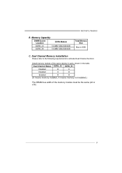
C. Memory Capacity DIMM Socket Location DDR3 Module DDR3_A1 512MB/1GB/2GB/4GB DDR3_B1 512MB/1GB/2GB/4GB Total Memory Size Max is 8GB. Dual Channel Status DDR3_A1 DDR3_B1 Disabled O X Disabled X O Enabled O O (O means memory installed, X means memory not installed.) The DRAM bus width of the same density in pairs, shown in the table. MCP6P3/N68S3 B. Dual Channel Memory installation Please refer to the following requirements to activate Dual Channel function: Install memory module of the memory module must be the same (x8 or x16) 9
C. Memory Capacity DIMM Socket Location DDR3 Module DDR3_A1 512MB/1GB/2GB/4GB DDR3_B1 512MB/1GB/2GB/4GB Total Memory Size Max is 8GB. Dual Channel Status DDR3_A1 DDR3_B1 Disabled O X Disabled X O Enabled O O (O means memory installed, X means memory not installed.) The DRAM bus width of the same density in pairs, shown in the table. MCP6P3/N68S3 B. Dual Channel Memory installation Please refer to the following requirements to activate Dual Channel function: Install memory module of the memory module must be the same (x8 or x16) 9
Setup Manual
Page 13
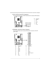
... Assignment 1 Ground 2 TX+ 3 TX4 Ground 5 RX6 RX+ 7 Ground 14 7 ATXPWR1: ATX Power Source Connector This connector allows user to SATA Controller with 4 channels SATA interface. MCP6P3/N68S3 SATA1~SATA4: Serial ATA Connectors The motherboard has a PCI to connect 24-pin power connector on the ATX power supply. 13 1 Pin Assignment 13 +3.3V...
... Assignment 1 Ground 2 TX+ 3 TX4 Ground 5 RX6 RX+ 7 Ground 14 7 ATXPWR1: ATX Power Source Connector This connector allows user to SATA Controller with 4 channels SATA interface. MCP6P3/N68S3 SATA1~SATA4: Serial ATA Connectors The motherboard has a PCI to connect 24-pin power connector on the ATX power supply. 13 1 Pin Assignment 13 +3.3V...
Setup Manual
Page 15
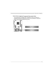
This PCI slot is equipped with 2 standard PCI slots. PCI1 PCI2 13 MCP6P3/N68S3 PCI1~PCI2: Peripheral Component Interconnect Slots This motherboard is designated as 32 bits. PCI stands for Peripheral Component Interconnect, and it is a bus standard for expansion cards.
This PCI slot is equipped with 2 standard PCI slots. PCI1 PCI2 13 MCP6P3/N68S3 PCI1~PCI2: Peripheral Component Interconnect Slots This motherboard is designated as 32 bits. PCI stands for Peripheral Component Interconnect, and it is a bus standard for expansion cards.
Setup Manual
Page 17
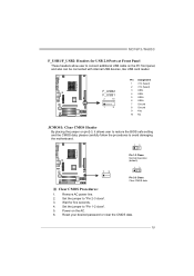
... ". 3. Power on the PC front panel, and also can be connected with internal USB devices, like USB card reader. Set the jumper to "Pin 2-3 close ". 5. MCP6P3/N68S3 F_USB1/F_USB2: Headers for five seconds. 4. F_USB2 F_USB1 2 10 1 9 Pin Assignment 1 +5V (fused) 2 +5V (fused) 3 USB4 USB5 USB+ 6 USB+ 7 Ground 8 Ground 9 Key 10 NC JCMOS1...
... ". 3. Power on the PC front panel, and also can be connected with internal USB devices, like USB card reader. Set the jumper to "Pin 2-3 close ". 5. MCP6P3/N68S3 F_USB1/F_USB2: Headers for five seconds. 4. F_USB2 F_USB1 2 10 1 9 Pin Assignment 1 +5V (fused) 2 +5V (fused) 3 USB4 USB5 USB+ 6 USB+ 7 Ground 8 Ground 9 Key 10 NC JCMOS1...

Setup Manual
Page 19
MCP6P3/N68S3 J_PRINT1: Printer Port Connector This header allows you to connector printer on the PC. 2 1 25 Pin Assignment 1 -Strobe 2 -ALF 3 Data 0 4 -Error 5 Data 1 6 -Init 7 Data 2 8 -Scltin 9 Data 3 10 Ground 11 Data 4 12 Ground 13 Data 5 Pin Assignment 14 Ground 15 Data 6 16 Ground 17 Data 7 18 Ground 19 -ACK 20 Ground 21 Busy 22 Ground 23 PE 24 Ground 25 SCLT 26 Key 1 7
MCP6P3/N68S3 J_PRINT1: Printer Port Connector This header allows you to connector printer on the PC. 2 1 25 Pin Assignment 1 -Strobe 2 -ALF 3 Data 0 4 -Error 5 Data 1 6 -Init 7 Data 2 8 -Scltin 9 Data 3 10 Ground 11 Data 4 12 Ground 13 Data 5 Pin Assignment 14 Ground 15 Data 6 16 Ground 17 Data 7 18 Ground 19 -ACK 20 Ground 21 Busy 22 Ground 23 PE 24 Ground 25 SCLT 26 Key 1 7

Setup Manual
Page 21
CHAPTER 4: RAID FUNCTIONS MCP6P3/N68S3 4.1 OPERATION SYSTEM Supports Windows XP, Windows Vista, and Windows 7. 4.2 RAID ARRAYS RAID supports the following types of disk capacity. 4.3 HOW RAID WORKS RAID 0: The controller "...
CHAPTER 4: RAID FUNCTIONS MCP6P3/N68S3 4.1 OPERATION SYSTEM Supports Windows XP, Windows Vista, and Windows 7. 4.2 RAID ARRAYS RAID supports the following types of disk capacity. 4.3 HOW RAID WORKS RAID 0: The controller "...

Setup Manual
Page 23
... Benefits Drives: Minimum 4, and maximum is 6 or 8, depending on the platform. Benefits: Optimizes for both fault tolerance and performance, allowing for automatic redundancy. MCP6P3/N68S3 RAID 0+1: RAID 0 drives can be simultaneously used with other RAID levels in a RAID 0+1 solution for improved performance plus resiliency.
... Benefits Drives: Minimum 4, and maximum is 6 or 8, depending on the platform. Benefits: Optimizes for both fault tolerance and performance, allowing for automatic redundancy. MCP6P3/N68S3 RAID 0+1: RAID 0 drives can be simultaneously used with other RAID levels in a RAID 0+1 solution for improved performance plus resiliency.
Setup Manual
Page 25
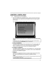
MCP6P3/N68S3 CHAPTER 5: USEFUL HELP 5.1 DRIVER INSTALLATION NOTE After you insert the Driver CD, please use file browser to locate and execute the file SETUP.EXE under ...
MCP6P3/N68S3 CHAPTER 5: USEFUL HELP 5.1 DRIVER INSTALLATION NOTE After you insert the Driver CD, please use file browser to locate and execute the file SETUP.EXE under ...
Setup Manual
Page 27
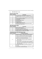
... error) 8 Display memory error (system video adapter) Troubleshooting POST BIOS Beep Codes Number of Beeps Troubleshooting Action 1, 3 Reseat the memory, or replace with the system. MCP6P3/N68S3 5.3 AMI BIOS BEEP CODE Boot Block Beep Codes Number of Beeps Description 1 No media present. (Insert diskette in floppy drive A:) 2 "AMIBOOT.ROM" file not found...
... error) 8 Display memory error (system video adapter) Troubleshooting POST BIOS Beep Codes Number of Beeps Troubleshooting Action 1, 3 Reseat the memory, or replace with the system. MCP6P3/N68S3 5.3 AMI BIOS BEEP CODE Boot Block Beep Codes Number of Beeps Description 1 No media present. (Insert diskette in floppy drive A:) 2 "AMIBOOT.ROM" file not found...
Setup Manual
Page 29
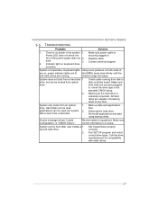
..." or "CMOS Failure." Make sure power cable is no power in ; System does not boot from an optical 1. There is Power LED does not shine; MCP6P3/N68S3 5.5 TROUBLESHOOTING Probable Solution 1. the securely plugged in the standard CMOS setup. Re-install applications and data using backup disks. Run SETUP program and select correct...
..." or "CMOS Failure." Make sure power cable is no power in ; System does not boot from an optical 1. There is Power LED does not shine; MCP6P3/N68S3 5.5 TROUBLESHOOTING Probable Solution 1. the securely plugged in the standard CMOS setup. Re-install applications and data using backup disks. Run SETUP program and select correct...

Setup Manual
Page 46
...Phenom II/ Athlon II 能です 95W) 2.0 2.0 GT/s FSB ート2.0 GeForce 6150 SE/nForce 430 (MCP6P3 GeForce 7025/nForce 630a (N68S3) DDR3 DIMM x 2 DDR3 8GB DDR3 800 / 1066 / 1333 各DIMMは 512MB/1GB/2GB/4GB DDR3を ...;ポート ITE 8718F Super I/O H/Wモニター Super I/O ITE GeForce 6150 SE/nForce 430 (MCP6P3) ス GeForce 7025/nForce 630a (N68S3) 512MBです(under OS) IDE 統合IDE Ultra DMA 33 / 66 / 100 / 133 PIO Mode...
...Phenom II/ Athlon II 能です 95W) 2.0 2.0 GT/s FSB ート2.0 GeForce 6150 SE/nForce 430 (MCP6P3 GeForce 7025/nForce 630a (N68S3) DDR3 DIMM x 2 DDR3 8GB DDR3 800 / 1066 / 1333 各DIMMは 512MB/1GB/2GB/4GB DDR3を ...;ポート ITE 8718F Super I/O H/Wモニター Super I/O ITE GeForce 6150 SE/nForce 430 (MCP6P3) ス GeForce 7025/nForce 630a (N68S3) 512MBです(under OS) IDE 統合IDE Ultra DMA 33 / 66 / 100 / 133 PIO Mode...