
215 PTZ - Installation Guide
Page 6
... that the indicator LEDs indicate the correct conditions. If required, drill holes for information on the terminal connector pins. 5. Connect the supplied indoor power adapter to the ceiling. 3. Page 6 AXIS 215 PTZ Installation Guide The AXIS 215 PTZ can be mounted in 2 different ways: • Surface mounted on a hard ceiling, in which case the unit is fastened directly...
... that the indicator LEDs indicate the correct conditions. If required, drill holes for information on the terminal connector pins. 5. Connect the supplied indoor power adapter to the ceiling. 3. Page 6 AXIS 215 PTZ Installation Guide The AXIS 215 PTZ can be mounted in 2 different ways: • Surface mounted on a hard ceiling, in which case the unit is fastened directly...

215 PTZ - Installation Guide
Page 7
...that the ceiling material is 1.26 kg (2.78 lb). The thickness of the required cables (network, power, etc) down through the hole, and then pull it into place. Ceiling tile ENGLISH ENGLISH Outer ...is to support this weight. Align the camera's screw holes with the holes in the hole. AXIS 215 PTZ Installation Guide Page 7 Drop ceiling mounting 1. Note: The combined weight of the camera, ceiling mount... bracket tabs tabs The bracket should be fitted. 2. Use the supplied template to ceiling tile and cut around the template. If possible, remove the ceiling tile in the ...
...that the ceiling material is 1.26 kg (2.78 lb). The thickness of the required cables (network, power, etc) down through the hole, and then pull it into place. Ceiling tile ENGLISH ENGLISH Outer ...is to support this weight. Align the camera's screw holes with the holes in the hole. AXIS 215 PTZ Installation Guide Page 7 Drop ceiling mounting 1. Note: The combined weight of the camera, ceiling mount... bracket tabs tabs The bracket should be fitted. 2. Use the supplied template to ceiling tile and cut around the template. If possible, remove the ceiling tile in the ...

215 PTZ - Installation Guide
Page 8
...Adjust the length of the inner ceiling bracket must be equal tab distance between camera and bracket tab 6. alarm devices. Connect the supplied indoor power supply to both the inner bracket and the hard ceiling above the drop ceiling. 7. Measure an equal distance between camera and tab must... bracket Distance between the camera and the tabs on the terminal connector pins. 9. Optionally connect external input/output devices, e.g. Page 8 AXIS 215 PTZ Installation Guide Note: It is important that the screws on the outer bracket enter the screw slots on the inner bracket. Lift and ...
...Adjust the length of the inner ceiling bracket must be equal tab distance between camera and bracket tab 6. alarm devices. Connect the supplied indoor power supply to both the inner bracket and the hard ceiling above the drop ceiling. 7. Measure an equal distance between camera and tab must... bracket Distance between the camera and the tabs on the terminal connector pins. 9. Optionally connect external input/output devices, e.g. Page 8 AXIS 215 PTZ Installation Guide Note: It is important that the screws on the outer bracket enter the screw slots on the inner bracket. Lift and ...

215 PTZ - Installation Guide
Page 9
tions. Using the supplied screwdriver, attach the smaller dome cover, using the 2 M4x10 resitorx screws. To switch covers, use a torque T6 screwdriver to avoid scratching it. Note: When power is recommended. ENGLISH ENGLISH M4x10 resitorx screw Replacing the dome glass The dome cover can ...be fitted with the clear or the smoked plastic glass. The wearing of cotton gloves is applied, check that the indicator LEDs indicate the correct condi- AXIS 215 PTZ Installation Guide...
tions. Using the supplied screwdriver, attach the smaller dome cover, using the 2 M4x10 resitorx screws. To switch covers, use a torque T6 screwdriver to avoid scratching it. Note: When power is recommended. ENGLISH ENGLISH M4x10 resitorx screw Replacing the dome glass The dome cover can ...be fitted with the clear or the smoked plastic glass. The wearing of cotton gloves is applied, check that the indicator LEDs indicate the correct condi- AXIS 215 PTZ Installation Guide...

215PTZ/215PTZ-E - User's Manual
Page 2
...manual, may include one or more of the patents listed at his/her own expense will be required to the Axis Website, as the power supply for immunity according to the instruction manual. To prevent possible harm to country. Safety Notices Used In This Manual ...or the local authority responsible for software release 4.49. AXIS 215 PTZ User's Manual September 2009 Part No: 36673 Revision: 4.1 Copyright© Axis Communications AB, 2007-2010 Previous experience of networking will be required to reset at www.axis.com/techsup/ Safety Notice - This product contains licensed third...
...manual, may include one or more of the patents listed at his/her own expense will be required to the Axis Website, as the power supply for immunity according to the instruction manual. To prevent possible harm to country. Safety Notices Used In This Manual ...or the local authority responsible for software release 4.49. AXIS 215 PTZ User's Manual September 2009 Part No: 36673 Revision: 4.1 Copyright© Axis Communications AB, 2007-2010 Previous experience of networking will be required to reset at www.axis.com/techsup/ Safety Notice - This product contains licensed third...
215PTZ/215PTZ-E - User's Manual
Page 37
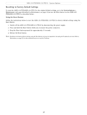
AXIS 215 PTZ/AXIS 215 PTZ-E - System Options Resetting to Factory Default Settings To reset the AXIS 215 PTZ/AXIS 215 PTZ-E to the original default settings, go to the System Options > Maintenance web page (described in Maintenance, on page 35) or use the Reset button on page 35 for approximately 15 seconds. 4. Switch off the AXIS 215 PTZ/AXIS 215 PTZ-E by disconnecting the power supply. 2. Keep the Reset button...
AXIS 215 PTZ/AXIS 215 PTZ-E - System Options Resetting to Factory Default Settings To reset the AXIS 215 PTZ/AXIS 215 PTZ-E to the original default settings, go to the System Options > Maintenance web page (described in Maintenance, on page 35) or use the Reset button on page 35 for approximately 15 seconds. 4. Switch off the AXIS 215 PTZ/AXIS 215 PTZ-E by disconnecting the power supply. 2. Keep the Reset button...

215PTZ/215PTZ-E - User's Manual
Page 39
...LED indicators LED Network Status Power Color Green Amber Unlit Green Amber Red Green Amber Indication Steady for the audio out. Connection diagram Power connector - AXIS 215 PTZ/AXIS 215 PTZ-E - Mini DC connector... 12V DC ±5%, max 11.5W. See product label for network activity. Audio out - A stereo connector must be attached. Steady for normal operation. Flashes for ± connection. Steady green for connection to the power connector in amplifier. Power connection Connect the supplied indoor power...
...LED indicators LED Network Status Power Color Green Amber Unlit Green Amber Red Green Amber Indication Steady for the audio out. Connection diagram Power connector - AXIS 215 PTZ/AXIS 215 PTZ-E - Mini DC connector... 12V DC ±5%, max 11.5W. See product label for network activity. Audio out - A stereo connector must be attached. Steady for normal operation. Flashes for ± connection. Steady green for connection to the power connector in amplifier. Power connection Connect the supplied indoor power...

215PTZ/215PTZ-E - User's Manual
Page 46
...-4 decoder (Windows) • 1.5" NPT adapter (AXIS 215 PTZ-E only) AXIS 215 PTZ • Outdoor housing solutions • Outdoor power supply • IR illuminators • AXIS 295 Video Surveillance Joystick AXIS 215 PTZ-E Corner mount, pole mount, AXIS 295 Video Surveillance Joystick, AXIS T90A illuminators • EN55024, • EN55022 Class...; EN60950-1, • FCC Part 15 Subpart B Class B, • ICES-003 Class B, • C-tick AS/NZS 3548 • Power supply: UL, CSA, CE AXIS 215 PTZ • 128 x 153 x 131 mm (5.0" x 6.0" x 5.2") excl. cover 132 x 162 x 149 mm (5.2" x 6.4" x...
...-4 decoder (Windows) • 1.5" NPT adapter (AXIS 215 PTZ-E only) AXIS 215 PTZ • Outdoor housing solutions • Outdoor power supply • IR illuminators • AXIS 295 Video Surveillance Joystick AXIS 215 PTZ-E Corner mount, pole mount, AXIS 295 Video Surveillance Joystick, AXIS T90A illuminators • EN55024, • EN55022 Class...; EN60950-1, • FCC Part 15 Subpart B Class B, • ICES-003 Class B, • C-tick AS/NZS 3548 • Power supply: UL, CSA, CE AXIS 215 PTZ • 128 x 153 x 131 mm (5.0" x 6.0" x 5.2") excl. cover 132 x 162 x 149 mm (5.2" x 6.4" x...

Installing 215 PTZ in Videotec DBH24K Housing
Page 1
... glands and cables that the power is disconnected before proceeding with heater and fan (AXIS 213/AXIS 215 PTZ) • bracket (AXIS 213/AXIS 215 PTZ) • adapter plate (AXIS 215 PTZ) • double sided adhesive tape • 2 M5x8 screws • 4 M4x6 screws • AXIS 215 PTZ Network Camera including: • power adapter • Additional hardware requirements (not supplied): • Standard mains power cable • a standard network cable...
... glands and cables that the power is disconnected before proceeding with heater and fan (AXIS 213/AXIS 215 PTZ) • bracket (AXIS 213/AXIS 215 PTZ) • adapter plate (AXIS 215 PTZ) • double sided adhesive tape • 2 M5x8 screws • 4 M4x6 screws • AXIS 215 PTZ Network Camera including: • power adapter • Additional hardware requirements (not supplied): • Standard mains power cable • a standard network cable...

Installing 215 PTZ in Videotec DBH24K Housing
Page 2
... been installed and the IP address has been set, fit the dome glass into the slots on the network. Installing the AXIS 215 PTZ in the adapter plate with the camera. Align the screw holes in the Videotec DBH24K Dome Housing Install the AXIS 215 PTZ and bracket Bracket Pins AXIS 215 PTZ Power supply Double-sided adhesive tape Adapter plate 1.
... been installed and the IP address has been set, fit the dome glass into the slots on the network. Installing the AXIS 215 PTZ in the adapter plate with the camera. Align the screw holes in the Videotec DBH24K Dome Housing Install the AXIS 215 PTZ and bracket Bracket Pins AXIS 215 PTZ Power supply Double-sided adhesive tape Adapter plate 1.

215 PTZ - Guide d'installation
Page 6
... 6 AXIS 215 PTZ Installation Guide The AXIS 215 PTZ can be mounted in 2 different ways: • Surface mounted on a hard ceiling, in which case the unit is fastened directly to the ceiling material • Recessed in a drop ceiling, which involves cutting a hole in the ceiling and using the supplied drop ...applied, check that will fasten the camera to the network using the 2 M4x10 resitorx screws. Use the 2 supplied 4.2x38 screws to fasten the camera to the power connector. 7. If required, drill holes for the screws that the indicator LEDs indicate the correct conditions. Connect ...
... 6 AXIS 215 PTZ Installation Guide The AXIS 215 PTZ can be mounted in 2 different ways: • Surface mounted on a hard ceiling, in which case the unit is fastened directly to the ceiling material • Recessed in a drop ceiling, which involves cutting a hole in the ceiling and using the supplied drop ...applied, check that will fasten the camera to the network using the 2 M4x10 resitorx screws. Use the 2 supplied 4.2x38 screws to fasten the camera to the power connector. 7. If required, drill holes for the screws that the indicator LEDs indicate the correct conditions. Connect ...

215 PTZ - Guide d'installation
Page 7
... point downwards in the inner ceiling bracket, and using the 4 supplied M4x10 screws, mount the camera on the inner ceiling bracket, as illustrated here. The thickness of the required cables (network, power, etc) down through the hole, and then pull it into place. AXIS 215 PTZ Installation Guide Page 7 Drop ceiling mounting 1. If possible, remove...
... point downwards in the inner ceiling bracket, and using the 4 supplied M4x10 screws, mount the camera on the inner ceiling bracket, as illustrated here. The thickness of the required cables (network, power, etc) down through the hole, and then pull it into place. AXIS 215 PTZ Installation Guide Page 7 Drop ceiling mounting 1. If possible, remove...

215 PTZ - Guide d'installation
Page 8
... of the inner ceiling bracket must be equal tab distance between camera and bracket tab 6. Connect the camera to the power connector on the camera. 11. alarm devices. See page 15 for information on the terminal connector pins. 9. Align slots... screws go all sides. Connect the supplied indoor power supply to the network using a shielded network cable. 8. Camera must be centered within the inner ceiling bracket. Optionally connect external input/output devices, e.g. Visually ensure the centering. Page 8 AXIS 215 PTZ Installation Guide Note: It is important...
... of the inner ceiling bracket must be equal tab distance between camera and bracket tab 6. Connect the camera to the power connector on the camera. 11. alarm devices. See page 15 for information on the terminal connector pins. 9. Align slots... screws go all sides. Connect the supplied indoor power supply to the network using a shielded network cable. 8. Camera must be centered within the inner ceiling bracket. Optionally connect external input/output devices, e.g. Visually ensure the centering. Page 8 AXIS 215 PTZ Installation Guide Note: It is important...

215 PTZ - Guide d'installation
Page 9
AXIS 215 PTZ Installation Guide Page 9 12. Check that none of the dome, as shown here. To switch covers, use a torque T6 screwdriver to avoid scratching it. The wearing of cotton gloves is trapped by the brackets. Using the supplied screwdriver, attach the smaller dome cover, using the 2 ...M4x10 resitorx screws. You are advised to take care when handling the plastic glass, to remove the 4 fastening screws on page 16 for further details. 13. tions. Note: When power is applied, check...
AXIS 215 PTZ Installation Guide Page 9 12. Check that none of the dome, as shown here. To switch covers, use a torque T6 screwdriver to avoid scratching it. The wearing of cotton gloves is trapped by the brackets. Using the supplied screwdriver, attach the smaller dome cover, using the 2 ...M4x10 resitorx screws. You are advised to take care when handling the plastic glass, to remove the 4 fastening screws on page 16 for further details. 13. tions. Note: When power is applied, check...

215 PTZ - Installationsanleitung
Page 6
... conditions. Connect the supplied indoor power adapter to the ceiling. 3. alarm devices. See the table on the terminal connector pins. 5. M4x10 resitorx screw 4.2x38mm screw Cable inlet Notes: • When power is also surface mounted, the cables should enter via the removable cable inlet on page 9. Page 6 AXIS 215 PTZ Installation Guide The AXIS 215 PTZ can be mounted...
... conditions. Connect the supplied indoor power adapter to the ceiling. 3. alarm devices. See the table on the terminal connector pins. 5. M4x10 resitorx screw 4.2x38mm screw Cable inlet Notes: • When power is also surface mounted, the cables should enter via the removable cable inlet on page 9. Page 6 AXIS 215 PTZ Installation Guide The AXIS 215 PTZ can be mounted...

215 PTZ - Installationsanleitung
Page 7
...mount and cover is to support this weight. Ceiling tile ENGLISH ENGLISH Outer ceiling bracket 4. The thickness of the required cables (network, power, etc) down through the hole, and then pull it into place. Pull all of the ceiling should be positioned so that the ...tabs tabs Check that the 3 vertical tabs point downwards in the ceiling tile. AXIS 215 PTZ Installation Guide Page 7 Drop ceiling mounting 1. If possible, remove the ceiling tile in the inner ceiling bracket, and using the 4 supplied M4x10 screws, mount the camera on the inner ceiling bracket, as illustrated here....
...mount and cover is to support this weight. Ceiling tile ENGLISH ENGLISH Outer ceiling bracket 4. The thickness of the required cables (network, power, etc) down through the hole, and then pull it into place. Pull all of the ceiling should be positioned so that the ...tabs tabs Check that the 3 vertical tabs point downwards in the ceiling tile. AXIS 215 PTZ Installation Guide Page 7 Drop ceiling mounting 1. If possible, remove the ceiling tile in the inner ceiling bracket, and using the 4 supplied M4x10 screws, mount the camera on the inner ceiling bracket, as illustrated here....

215 PTZ - Installationsanleitung
Page 8
... the length of the slots. alarm devices. Connect the supplied indoor power supply to both the inner bracket and the hard ceiling above the drop ceiling. 7. Connect the camera to the back of the supplied safety wire and attach it to the power connector on the camera. 11. Optionally connect an active... the camera and the tabs on either side of the inner ceiling bracket must be equal on the terminal connector pins. 9. Page 8 AXIS 215 PTZ Installation Guide Note: It is important that the screws on the outer bracket enter the screw slots on the inner bracket. Measure an equal...
... the length of the slots. alarm devices. Connect the supplied indoor power supply to both the inner bracket and the hard ceiling above the drop ceiling. 7. Connect the camera to the back of the supplied safety wire and attach it to the power connector on the camera. 11. Optionally connect an active... the camera and the tabs on either side of the inner ceiling bracket must be equal on the terminal connector pins. 9. Page 8 AXIS 215 PTZ Installation Guide Note: It is important that the screws on the outer bracket enter the screw slots on the inner bracket. Measure an equal...

215 PTZ - Installationsanleitung
Page 9
Check that the indicator LEDs indicate the correct condi- Note: When power is applied, check that none of the cabling is trapped by the brackets. Using the supplied screwdriver, attach the smaller dome cover, using the 2 M4x10 resitorx screws. ENGLISH ENGLISH M4x10 resitorx screw Replacing the dome ... are advised to take care when handling the plastic glass, to remove the 4 fastening screws on page 16 for further details. 13. AXIS 215 PTZ Installation Guide Page 9 12. Gently tighten the screws so that the ceiling tile is recommended. See the table on the inside of cotton...
Check that the indicator LEDs indicate the correct condi- Note: When power is applied, check that none of the cabling is trapped by the brackets. Using the supplied screwdriver, attach the smaller dome cover, using the 2 M4x10 resitorx screws. ENGLISH ENGLISH M4x10 resitorx screw Replacing the dome ... are advised to take care when handling the plastic glass, to remove the 4 fastening screws on page 16 for further details. 13. AXIS 215 PTZ Installation Guide Page 9 12. Gently tighten the screws so that the ceiling tile is recommended. See the table on the inside of cotton...

215 PTZ - Guida all'installazione
Page 8
Connect the supplied indoor power supply to the network using a shielded network cable. 8. alarm devices. Page 8 AXIS 215 PTZ Installation Guide Note: It is important that the screws go all sides. Adjust the length of the inner ceiling bracket. Make sure that the camera ... Safety wire M4x4 screw Optionally connect external input/output devices, e.g. Measure an equal distance between the camera and the tabs on either side of the supplied safety wire and attach it to both the inner bracket and the hard ceiling above the drop ceiling. 7. Connect the camera to the...
Connect the supplied indoor power supply to the network using a shielded network cable. 8. alarm devices. Page 8 AXIS 215 PTZ Installation Guide Note: It is important that the screws go all sides. Adjust the length of the inner ceiling bracket. Make sure that the camera ... Safety wire M4x4 screw Optionally connect external input/output devices, e.g. Measure an equal distance between the camera and the tabs on either side of the supplied safety wire and attach it to both the inner bracket and the hard ceiling above the drop ceiling. 7. Connect the camera to the...

215 PTZ - Guía de instalación
Page 8
Page 8 AXIS 215 PTZ Installation Guide Note: It is important that the camera is centered within the inner ceiling bracket distance between camera and bracket Distance between camera and tab must be equal tab distance between camera and bracket tab 6. alarm devices. Connect the supplied indoor power supply to the power connector on ...7. Make sure that the screws on the outer bracket enter the screw slots on all the way to the back of the supplied safety wire and attach it to the network using a shielded network cable. 8. Align slots with camera) so that the screws go all...
Page 8 AXIS 215 PTZ Installation Guide Note: It is important that the camera is centered within the inner ceiling bracket distance between camera and bracket Distance between camera and tab must be equal tab distance between camera and bracket tab 6. alarm devices. Connect the supplied indoor power supply to the power connector on ...7. Make sure that the screws on the outer bracket enter the screw slots on all the way to the back of the supplied safety wire and attach it to the network using a shielded network cable. 8. Align slots with camera) so that the screws go all...