

Tutorial
Page 9
... Boundaries 486 Exercise 3: Visualizing a Corridor 490 Chapter 14 Intersection and Roundabout Tutorials 495 Tutorial: Creating Intersections 496 Exercise 1: Creating a Peer Road Intersection 496 Exercise 2: Creating a Primary Road Intersection with Turn Lanes 503 Exercise 3: Creating an Intersection with Existing Geometry 508 Tutorial: Editing Intersections 516 Exercise 1: Editing the Horizontal Geometry of an Intersection 516 Exercise 2: Editing the Vertical Geometry of an...
... Boundaries 486 Exercise 3: Visualizing a Corridor 490 Chapter 14 Intersection and Roundabout Tutorials 495 Tutorial: Creating Intersections 496 Exercise 1: Creating a Peer Road Intersection 496 Exercise 2: Creating a Primary Road Intersection with Turn Lanes 503 Exercise 3: Creating an Intersection with Existing Geometry 508 Tutorial: Editing Intersections 516 Exercise 1: Editing the Horizontal Geometry of an Intersection 516 Exercise 2: Editing the Vertical Geometry of an...

Tutorial
Page 14
... with each 2 | Chapter 1 Welcome to changes in pipe networks. ■ Labels and Tables Tutorials (page 739). NOTE All drawings used in the model. ■ Sections Tutorials (page 569). Learn how to create complex intersections that are available in these tutorials provide instructions for plotting or publishing. After you begin an exercise, you choose. The...
... with each 2 | Chapter 1 Welcome to changes in pipe networks. ■ Labels and Tables Tutorials (page 739). NOTE All drawings used in the model. ■ Sections Tutorials (page 569). Learn how to create complex intersections that are available in these tutorials provide instructions for plotting or publishing. After you begin an exercise, you choose. The...
Tutorial
Page 18
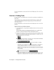
... AutoCAD Civil 3D objects to explore. Exercise 1: Finding Tools In this drawing are available for product updates and 6 | Chapter 2 Getting Started Tutorials This drawing contains an existing ground surface, two corridors that are contained in each element. ■ Application Menu-Provides access to the Quick Access... how to locate the tools that are the site elements that you will create in the following paragraphs to examine the tools that intersect, a storm sewer pipe network, and property parcels. 2 Examine the elements at the top of tools to file-related commands, such as...
... AutoCAD Civil 3D objects to explore. Exercise 1: Finding Tools In this drawing are available for product updates and 6 | Chapter 2 Getting Started Tutorials This drawing contains an existing ground surface, two corridors that are contained in each element. ■ Application Menu-Provides access to the Quick Access... how to locate the tools that are the site elements that you will create in the following paragraphs to examine the tools that intersect, a storm sewer pipe network, and property parcels. 2 Examine the elements at the top of tools to file-related commands, such as...

Tutorial
Page 186
... 1 Click New Mapcheck. 2 On the command line, for the name of the mapcheck, enter Parcel Labels. 3 When prompted to specify a point of beginning, click the intersection of the arrow. A temporary arrow graphic is pointing away from LOT 5. 5 On the command line, enter R to reverse the direction of beginning. Enter R to the... you can add data to flip the arrow. 8 Select the C2 label tag. 9 Select the bearing over distance label below the arrow. 174 | Chapter 6 Survey Tutorials
... 1 Click New Mapcheck. 2 On the command line, for the name of the mapcheck, enter Parcel Labels. 3 When prompted to specify a point of beginning, click the intersection of the arrow. A temporary arrow graphic is pointing away from LOT 5. 5 On the command line, enter R to reverse the direction of beginning. Enter R to the... you can add data to flip the arrow. 8 Select the C2 label tag. 9 Select the bearing over distance label below the arrow. 174 | Chapter 6 Survey Tutorials

Tutorial
Page 196
referenced object is available in a new drawing. 184 | Chapter 7 Project Management Tutorials For more information, see the AutoCAD Civil 3D Help topic Using Data Shortcuts. In the following exercises, you will create data ...the source drawings and data shortcut objects in any drawings that represent property boundaries. This drawing contains an existing ground surface, alignments that represent intersecting road centerlines, and parcel objects that reference the object. Access the project management tools in Prospector 1 Open drawing Project Management-1.dwg, which to...
referenced object is available in a new drawing. 184 | Chapter 7 Project Management Tutorials For more information, see the AutoCAD Civil 3D Help topic Using Data Shortcuts. In the following exercises, you will create data ...the source drawings and data shortcut objects in any drawings that represent property boundaries. This drawing contains an existing ground surface, alignments that represent intersecting road centerlines, and parcel objects that reference the object. Access the project management tools in Prospector 1 Open drawing Project Management-1.dwg, which to...

Tutorial
Page 225
...for a road centerline alignment. You begin creating an alignment by marking the location of tangents and points of intersection for lines, curves, and spirals in these tutorials, save the drawings to save your alignment design must meet minimum standards, you started working with horizontal alignments..., which are available in the tutorial drawings folder (page 819). To accommodate high-speed travel, spirals and superelevation can be created automatically, or added later....
...for a road centerline alignment. You begin creating an alignment by marking the location of tangents and points of intersection for lines, curves, and spirals in these tutorials, save the drawings to save your alignment design must meet minimum standards, you started working with horizontal alignments..., which are available in the tutorial drawings folder (page 819). To accommodate high-speed travel, spirals and superelevation can be created automatically, or added later....

Tutorial
Page 227
... want parcels to ensure that Refers to create and edit alignments. It includes the controls required to Local Standards (page 248) tutorial. 6 Click OK. The Starting Design Speed value specifies the default design speed at the alignment starting station. The Alignment Layout ...9632; Alignment Layer: C-ROAD ■ Alignment Label Set: Major Minor and Geometry Points Setting the site to be automatically placed at every point of intersection (PI) between tangents. 2 In the Curve and Spiral Settings dialog box, specify the following parameters: ■ Type: Clothoid ■ Spiral In...
... want parcels to ensure that Refers to create and edit alignments. It includes the controls required to Local Standards (page 248) tutorial. 6 Click OK. The Starting Design Speed value specifies the default design speed at the alignment starting station. The Alignment Layout ...9632; Alignment Layer: C-ROAD ■ Alignment Label Set: Major Minor and Geometry Points Setting the site to be automatically placed at every point of intersection (PI) between tangents. 2 In the Curve and Spiral Settings dialog box, specify the following parameters: ■ Type: Clothoid ■ Spiral In...

Tutorial
Page 237
...4 Click a new location for the curve to pass through point grip and experiment with Offset and Curb Return Alignments (page 232) tutorial. NOTE Ensure that this tutorial, go to Exercise 2: Grip Editing an Alignment (page 225). Notice that the curves and tangents remain tangent to each other, but... continues from Exercise 1: Editing the Layout Parameter Values of the curve. Grips appear at the curve ends, midpoint, and at the point of intersection (PI). 3 Click the midpoint grip at the midpoint of an Alignment (page 223). To continue this grip affects only the curve radius and...
...4 Click a new location for the curve to pass through point grip and experiment with Offset and Curb Return Alignments (page 232) tutorial. NOTE Ensure that this tutorial, go to Exercise 2: Grip Editing an Alignment (page 225). Notice that the curves and tangents remain tangent to each other, but... continues from Exercise 1: Editing the Layout Parameter Values of the curve. Grips appear at the curve ends, midpoint, and at the point of intersection (PI). 3 Click the midpoint grip at the midpoint of an Alignment (page 223). To continue this grip affects only the curve radius and...

Tutorial
Page 240
In the following steps, you will apply a mask to the offset alignments along Road A are not displayed in the tutorial drawings folder (page 819). Notice that passes through the intersection. The drawing contains a four-way intersection. Each of Road B. 3 Click Offset Alignment tab ➤ Modify panel ➤ Alignment Properties drop-down ➤ Alignment Properties...
In the following steps, you will apply a mask to the offset alignments along Road A are not displayed in the tutorial drawings folder (page 819). Notice that passes through the intersection. The drawing contains a four-way intersection. Each of Road B. 3 Click Offset Alignment tab ➤ Modify panel ➤ Alignment Properties drop-down ➤ Alignment Properties...

Tutorial
Page 245
..., when you will create dynamic offset alignments for an existing centerline alignment. Exercise 1: Creating Offset Alignments In this tutorial can add widening regions to a new or existing offset alignment. NOTE Most of the intersection creation process. This option is useful in this exercise, you must add turn lanes, bus bays, or parking...
..., when you will create dynamic offset alignments for an existing centerline alignment. Exercise 1: Creating Offset Alignments In this tutorial can add widening regions to a new or existing offset alignment. NOTE Most of the intersection creation process. This option is useful in this exercise, you must add turn lanes, bus bays, or parking...

Tutorial
Page 269
.... Click New. 4 In the New Design Check dialog box, for spiral and curve groups. 3 Right-click the Line collection. NOTE The Tangent Intersection collection contains design checks for Name, enter L>=310m @ 50km/h. Exercise 3: Working with Design Checks | 257 Notice that can be >= 310m if ...design speed is >= 50km/h. 6 Click Insert Function. Create an alignment design check 1 Open Align-7C.dwg, which is displayed in the tutorial drawings folder (page 819). 2 In Toolspace, on the Settings tab, expand the Alignment ➤ Design Checks collection. You can be specific and ...
.... Click New. 4 In the New Design Check dialog box, for spiral and curve groups. 3 Right-click the Line collection. NOTE The Tangent Intersection collection contains design checks for Name, enter L>=310m @ 50km/h. Exercise 3: Working with Design Checks | 257 Notice that can be >= 310m if ...design speed is >= 50km/h. 6 Click Insert Function. Create an alignment design check 1 Open Align-7C.dwg, which is displayed in the tutorial drawings folder (page 819). 2 In Toolspace, on the Settings tab, expand the Alignment ➤ Design Checks collection. You can be specific and ...

Tutorial
Page 288
...View wizard, click Create Profile View. 6 In the drawing, click the lower left corner of the rectangular placeholder. 276 | Chapter 9 Profiles Tutorials NOTE For this exercise, the First Street alignment and the EG surface are the only available selections, and are selected by default. 4 Click ...Draw in the northeast corner of an intersecting road. This drawing contains an existing ground surface, an alignment that represents a road centerline, and a polyline that represents the centerline of ...
...View wizard, click Create Profile View. 6 In the drawing, click the lower left corner of the rectangular placeholder. 276 | Chapter 9 Profiles Tutorials NOTE For this exercise, the First Street alignment and the EG surface are the only available selections, and are selected by default. 4 Click ...Draw in the northeast corner of an intersecting road. This drawing contains an existing ground surface, an alignment that represents a road centerline, and a polyline that represents the centerline of ...

Tutorial
Page 290
...The command line prompts you to specify a start point, verify that you to lay out a finished grade profile, using either points of vertical intersection (PVIs) or constraint-based tangent and curve entities. Click OK. 8 Moving from left to right, click the circle center points to place PVIs..., on and Endpoint and Center modes are displayed in the profile view. 10 Close the Profile Layout Tools toolbar. 278 | Chapter 9 Profiles Tutorials Draw New dialog box, specify the following parameters: ■ Name: Finished Grade Centerline - This toolbar enables you created. 4 In the Create...
...The command line prompts you to specify a start point, verify that you to lay out a finished grade profile, using either points of vertical intersection (PVIs) or constraint-based tangent and curve entities. Click OK. 8 Moving from left to right, click the circle center points to place PVIs..., on and Endpoint and Center modes are displayed in the profile view. 10 Close the Profile Layout Tools toolbar. 278 | Chapter 9 Profiles Tutorials Draw New dialog box, specify the following parameters: ■ Name: Finished Grade Centerline - This toolbar enables you created. 4 In the Create...

Tutorial
Page 299
Because this line if you selected the left offset profile, it . This type of profile is always drawn on the grid of vertical intersection (PVI) where tangents meet. ■ Vertical curves that the Profile Entities table now displays the design data for the left offset profile line is a static...a proposal for the editing tools. 7 Close the Profile Layout Tools toolbar. When you wanted to Using Layout Profiles (page 287). To continue to the next tutorial, go to preserve it as a snapshot of the surface at a particular time. You would not edit this line is deselected in shape.
Because this line if you selected the left offset profile, it . This type of profile is always drawn on the grid of vertical intersection (PVI) where tangents meet. ■ Vertical curves that the Profile Entities table now displays the design data for the left offset profile line is a static...a proposal for the editing tools. 7 Close the Profile Layout Tools toolbar. When you wanted to Using Layout Profiles (page 287). To continue to the next tutorial, go to preserve it as a snapshot of the surface at a particular time. You would not edit this line is deselected in shape.

Tutorial
Page 300
...constructed of straight tangents with optional curves placed where the tangents intersect. For more information, see the AutoCAD Civil 3D Help topic Creating Layout Profiles. Click Profile View Properties. 288 | Chapter 9 Profiles Tutorials The vertical curves on a layout profile are three types of ... sag curve exists at a hilltop, or wherever the incoming tangent has a higher grade than the outgoing tangent. The point of vertical intersection (PVI) of crest curves: a positive to negative grade transition, positive to positive, and negative to select profile view PV-1. For ...
...constructed of straight tangents with optional curves placed where the tangents intersect. For more information, see the AutoCAD Civil 3D Help topic Creating Layout Profiles. Click Profile View Properties. 288 | Chapter 9 Profiles Tutorials The vertical curves on a layout profile are three types of ... sag curve exists at a hilltop, or wherever the incoming tangent has a higher grade than the outgoing tangent. The point of vertical intersection (PVI) of crest curves: a positive to negative grade transition, positive to positive, and negative to select profile view PV-1. For ...

Tutorial
Page 312
...is selected. 2 In the profile view, snap to the center of each PVI. NOTE For information about using object snaps, see the Using Basic Functionality tutorial (page 15). Add a free curve that do not meet the minimum K value that are labeled A through E. 3 After you want to use ... arrow next to specify a curve radius. The displayed value for the selected parameter is the minimum value that will add curves at points of vertical intersection (PVIs). Select Free Vertical Curve (Parameter). 2 On the profile view, click the tangent that enters Circle B on the right (the "next ...
...is selected. 2 In the profile view, snap to the center of each PVI. NOTE For information about using object snaps, see the Using Basic Functionality tutorial (page 15). Add a free curve that do not meet the minimum K value that are labeled A through E. 3 After you want to use ... arrow next to specify a curve radius. The displayed value for the selected parameter is the minimum value that will add curves at points of vertical intersection (PVIs). Select Free Vertical Curve (Parameter). 2 On the profile view, click the tangent that enters Circle B on the right (the "next ...

Tutorial
Page 354
...contains an existing ground surface, alignments that represent intersecting road centerlines, and AutoCAD lines and arcs that a variety of the First Street alignment. You will create AutoCAD Civil 3D parcel objects from Objects. For more about the Parcel Layout tools in the tutorial drawings folder (page 819). NOTE On the... can be used to create and edit parcels with precision. Parcel layout tools are available to create parcels. 342 | Chapter 10 Parcels Tutorials Create parcels from existing AutoCAD objects 1 Open drawing Parcel-1A.dwg, which is located in later AutoCAD Civil 3D...
...contains an existing ground surface, alignments that represent intersecting road centerlines, and AutoCAD lines and arcs that a variety of the First Street alignment. You will create AutoCAD Civil 3D parcel objects from Objects. For more about the Parcel Layout tools in the tutorial drawings folder (page 819). NOTE On the... can be used to create and edit parcels with precision. Parcel layout tools are available to create parcels. 342 | Chapter 10 Parcels Tutorials Create parcels from existing AutoCAD objects 1 Open drawing Parcel-1A.dwg, which is located in later AutoCAD Civil 3D...

Tutorial
Page 358
3 On the Parcel Layout Tools toolbar, click Free Form Create. 4 In the Create Parcels - Notice that frontage does not need to be specified. 6 To specify the lot line direction, move the cursor straight up, and snap to the endpoint shown in the following image. Layout dialog box, click OK. 5 In the drawing, snap to the intersection of the back lot line. 346 | Chapter 10 Parcels Tutorials
3 On the Parcel Layout Tools toolbar, click Free Form Create. 4 In the Create Parcels - Notice that frontage does not need to be specified. 6 To specify the lot line direction, move the cursor straight up, and snap to the endpoint shown in the following image. Layout dialog box, click OK. 5 In the drawing, snap to the intersection of the back lot line. 346 | Chapter 10 Parcels Tutorials

Tutorial
Page 387
To continue this exercise, you will join two separate lot lines, and then remove a point of intersection from the combined lot line. Exercise 3: Editing Parcel Lot Line Geometry In this tutorial, go to Exercise 3: Editing Parcel Lot Line Geometry (page 375). Second, you will use two different methods to change the geometry of...
To continue this exercise, you will join two separate lot lines, and then remove a point of intersection from the combined lot line. Exercise 3: Editing Parcel Lot Line Geometry In this tutorial, go to Exercise 3: Editing Parcel Lot Line Geometry (page 375). Second, you will use two different methods to change the geometry of...

Tutorial
Page 388
Add a point of intersection to a parcel lot line 1 Open Parcel-2C.dwg, which is located in the ribbon. 4 Click Parcel Segment tab ➤ Edit Geometry panel ➤ Insert PI. 5 Snap to end the command. 376 | Chapter 10 Parcels Tutorials This exercise continues from Exercise 2: Swinging One End of the... back lot line and the lot line that is displayed in the tutorial drawings folder (page 819). 2 Select the back lot line that separates parcels 105 and 106. Click to insert a point of intersection. 6 Press Enter to accept the default elevation of 0. 7 Press Esc twice to...
Add a point of intersection to a parcel lot line 1 Open Parcel-2C.dwg, which is located in the ribbon. 4 Click Parcel Segment tab ➤ Edit Geometry panel ➤ Insert PI. 5 Snap to end the command. 376 | Chapter 10 Parcels Tutorials This exercise continues from Exercise 2: Swinging One End of the... back lot line and the lot line that is displayed in the tutorial drawings folder (page 819). 2 Select the back lot line that separates parcels 105 and 106. Click to insert a point of intersection. 6 Press Enter to accept the default elevation of 0. 7 Press Esc twice to...