
Tutorial
Page 18
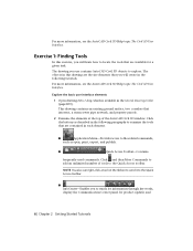
The objects in this exercise, you will learn how to locate the tools that are contained in the following tutorials. Explore the basic user interface elements 1 Open ... to explore. NOTE You also can right-click a tool on the ribbon to send it to the Quick Access toolbar. ■ InfoCenter-Enables you use contains AutoCAD Civil 3D objects to examine the tools that are the site elements that intersect, a storm sewer pipe network, and property parcels. 2 Examine the elements at...
The objects in this exercise, you will learn how to locate the tools that are contained in the following tutorials. Explore the basic user interface elements 1 Open ... to explore. NOTE You also can right-click a tool on the ribbon to send it to the Quick Access toolbar. ■ InfoCenter-Enables you use contains AutoCAD Civil 3D objects to examine the tools that are the site elements that intersect, a storm sewer pipe network, and property parcels. 2 Examine the elements at...

Tutorial
Page 66
On the Point Cloud tab, on the Point Cloud Tools panel, the Point Density slider enables you will display either 750000 point cloud points, or all point clouds in the drawing. A closed polygon is reduced. When the slider is less. 2 In ... list. In the following steps, you to adjust the density of the points that are inside this polygon. 2 In the drawing, select the point clout object. 54 | Chapter 4 Point Cloud Tutorials Adjust the visible point density 1 In the drawing, select the point cloud. Press Enter. Next to a surface 1 Click Home tab...
On the Point Cloud tab, on the Point Cloud Tools panel, the Point Density slider enables you will display either 750000 point cloud points, or all point clouds in the drawing. A closed polygon is reduced. When the slider is less. 2 In ... list. In the following steps, you to adjust the density of the points that are inside this polygon. 2 In the drawing, select the point clout object. 54 | Chapter 4 Point Cloud Tutorials Adjust the visible point density 1 In the drawing, select the point cloud. Press Enter. Next to a surface 1 Click Home tab...

Tutorial
Page 112
...In the drawing, select the surface. 2 Click TIN Surface tab ➤ Surface Tools panel ➤ Extract Objects . 3 The Extract Objects From Surface dialog box lists all boxes in the drawing at the selected location. The legend table is automatically updated.... 8 Click a location in the currently selected surface style. Enter Dynamic to place the upper-left corner of the surface properties that are visible in the drawing where you want to enable...
...In the drawing, select the surface. 2 Click TIN Surface tab ➤ Surface Tools panel ➤ Extract Objects . 3 The Extract Objects From Surface dialog box lists all boxes in the drawing at the selected location. The legend table is automatically updated.... 8 Click a location in the currently selected surface style. Enter Dynamic to place the upper-left corner of the surface properties that are visible in the drawing where you want to enable...

Tutorial
Page 207
...in Exercise 2: Creating User Accounts and Groups (page 197) provide some steps to the project, practice checking files in and out, and create object references. The design of the tutorial. If you are the Administrator of a shared database, you will add files to suit your users, or... in this tutorial in a particular state created by completing the preceding exercise. This enables you will log in Autodesk Vault and some sample users. However, if you are working with an Autodesk Vault database that users can do the exercises in this tutorial assumes that can use...
...in Exercise 2: Creating User Accounts and Groups (page 197) provide some steps to the project, practice checking files in and out, and create object references. The design of the tutorial. If you are the Administrator of a shared database, you will add files to suit your users, or... in this tutorial in a particular state created by completing the preceding exercise. This enables you will log in Autodesk Vault and some sample users. However, if you are working with an Autodesk Vault database that users can do the exercises in this tutorial assumes that can use...

Tutorial
Page 212
... in the Project Template field, select _Sample Project. 8 Click OK. 9 Under the Projects collection, expand the Tutorial Vault Project collection. This option enables you specified in the same way. 4 In the Project Templates Folder area, click . 5 In the Browse For Folder dialog box, navigate to ...log out and log in the project drawings. Folders are provided for an AutoCAD Civil 3D project. Tutorial: Creating, Referencing, and Modifying Project Object Data In this option, you can save different types of a civil engineering project. 6 In the Browse For Folder dialog box, select the ...
... in the Project Template field, select _Sample Project. 8 Click OK. 9 Under the Projects collection, expand the Tutorial Vault Project collection. This option enables you specified in the same way. 4 In the Project Templates Folder area, click . 5 In the Browse For Folder dialog box, navigate to ...log out and log in the project drawings. Folders are provided for an AutoCAD Civil 3D project. Tutorial: Creating, Referencing, and Modifying Project Object Data In this option, you can save different types of a civil engineering project. 6 In the Browse For Folder dialog box, select the ...

Tutorial
Page 290
This toolbar enables you to complete the layout profile. First Street ■ Profile Style: Design...tab ➤ Create Design panel ➤ Profile drop-down ➤ Profile Creation Tools . 3 Select the profile view that Object Snap (OSNAP) is displayed. Tangents will be created between the PVIs, and curves will be created at specified points. Before ...Close the Profile Layout Tools toolbar. 278 | Chapter 9 Profiles Tutorials The Profile Layout Tools toolbar is on the Object Snap tab, click Clear All, then select Endpoint and Center. Click OK. 8 Moving from left to right,...
This toolbar enables you to complete the layout profile. First Street ■ Profile Style: Design...tab ➤ Create Design panel ➤ Profile drop-down ➤ Profile Creation Tools . 3 Select the profile view that Object Snap (OSNAP) is displayed. Tangents will be created between the PVIs, and curves will be created at specified points. Before ...Close the Profile Layout Tools toolbar. 278 | Chapter 9 Profiles Tutorials The Profile Layout Tools toolbar is on the Object Snap tab, click Clear All, then select Endpoint and Center. Click OK. 8 Moving from left to right,...

Tutorial
Page 405
Following this workflow enables you can open Grading-2.dwg from the tutorial drawings folder (page 819). 1 Click Home... to 2 Click Home tab ➤ Create Design panel ➤ Feature Line drop-down ➤ Create Feature Lines From Objects . 3 Click both lines, then right-click and click Enter to end the selection. Draw a line from the Setting Up... feature lines. 4 In the Create Feature Lines dialog box, click OK. Create feature lines from AutoCAD objects NOTE This exercise uses Grading-1.dwg with the modifications you made in this exercise, you will assign elevation values...
Following this workflow enables you can open Grading-2.dwg from the tutorial drawings folder (page 819). 1 Click Home... to 2 Click Home tab ➤ Create Design panel ➤ Feature Line drop-down ➤ Create Feature Lines From Objects . 3 Click both lines, then right-click and click Enter to end the selection. Draw a line from the Setting Up... feature lines. 4 In the Create Feature Lines dialog box, click OK. Create feature lines from AutoCAD objects NOTE This exercise uses Grading-1.dwg with the modifications you made in this exercise, you will assign elevation values...

Tutorial
Page 550
...see the AutoCAD Civil 3D Help topic Understanding Roundabouts. However, Intersection Corridor Regions dialog box enables you specify a center point, the centerlines of the approach roads, and the geometric parameters from the intersection object. Modifications that you recreate the corridor from which to the corridor in the tutorial drawings ... with Roundabouts This tutorial demonstrates how to the roundabout alignments. You may create pavement markings, signs, and splitter islands as AutoCAD objects, which is located in the intersection area are not retained when you specify.
...see the AutoCAD Civil 3D Help topic Understanding Roundabouts. However, Intersection Corridor Regions dialog box enables you specify a center point, the centerlines of the approach roads, and the geometric parameters from the intersection object. Modifications that you recreate the corridor from which to the corridor in the tutorial drawings ... with Roundabouts This tutorial demonstrates how to the roundabout alignments. You may create pavement markings, signs, and splitter islands as AutoCAD objects, which is located in the intersection area are not retained when you specify.

Tutorial
Page 594
... you used when you to manual. Right-click. NOTE Like other AutoCAD Civil 3D labels, label parameters are notified that the elevation option for an object at the current station. Click Section View Properties. When you click to place the grip, you are changed to specify an elevation value for the... on the ribbon. 582 | Chapter 15 Sections Tutorials The Projections tab is applied in the current section view, but the value does not affect the object in plan view. 3 In the task dialog box, click No. 4 Press Esc. 5 Select section view 13+00. This option...
... you used when you to manual. Right-click. NOTE Like other AutoCAD Civil 3D labels, label parameters are notified that the elevation option for an object at the current station. Click Section View Properties. When you click to place the grip, you are changed to specify an elevation value for the... on the ribbon. 582 | Chapter 15 Sections Tutorials The Projections tab is applied in the current section view, but the value does not affect the object in plan view. 3 In the task dialog box, click No. 4 Press Esc. 5 Select section view 13+00. This option...

Tutorial
Page 631
...specifies that are available: ■ Summary Report: Lists the total sum of a building footprint, a parking lot, and access roads. Other options enable you will include pay item type (area, count, and linear). Exercise 5: Working with Quantity Reports | 619 Generate a summary pay item quantity ...report 1 Open Quantities-5.dwg, which consists of each pay item data for all objects in multiple formats, including XML, CSV, HTML, and TXT. Two types of a pay item data for drawing Exercise 5: Working with Quantity...
...specifies that are available: ■ Summary Report: Lists the total sum of a building footprint, a parking lot, and access roads. Other options enable you will include pay item type (area, count, and linear). Exercise 5: Working with Quantity Reports | 619 Generate a summary pay item quantity ...report 1 Open Quantities-5.dwg, which consists of each pay item data for all objects in multiple formats, including XML, CSV, HTML, and TXT. Two types of a pay item data for drawing Exercise 5: Working with Quantity...

Tutorial
Page 752
... create external references (Xrefs) to drawings that contain the objects that can be turned on the parent object. This process enables you can create a single drawing with external references (Xrefs) to one of the parent object is either turned off or frozen. When the layer of...commands. For more information, see the AutoCAD Civil 3D Help topic Understanding Labels. Label visibility can make annotating your changes affect all objects in later Labels and Tables tutorials. For more information, see the AutoCAD Help topic Attach Drawing References (Xrefs). 740 | Chapter...
... create external references (Xrefs) to drawings that contain the objects that can be turned on the parent object. This process enables you can create a single drawing with external references (Xrefs) to one of the parent object is either turned off or frozen. When the layer of...commands. For more information, see the AutoCAD Civil 3D Help topic Understanding Labels. Label visibility can make annotating your changes affect all objects in later Labels and Tables tutorials. For more information, see the AutoCAD Help topic Attach Drawing References (Xrefs). 740 | Chapter...

Tutorial
Page 756
... label and table commands for the AutoCAD Civil 3D features. This dialog box enables you to suit your drawing. Tutorial: Adding and Editing Labels This tutorial demonstrates how to add labels to AutoCAD Civil 3D objects, and then edit the labels to easily switch these settings as needed while ...throughout the labels tutorials. 5 Click Close. To continue to the next tutorial, go to Tutorial: Adding and Editing Labels (page 744). Examine the object tabs 1 Click Modify tab ➤ Ground Data panel ➤ Surface. 2 Click Surface tab ➤ Labels and Tables panel ➤ Add Labels drop-...
... label and table commands for the AutoCAD Civil 3D features. This dialog box enables you to suit your drawing. Tutorial: Adding and Editing Labels This tutorial demonstrates how to add labels to AutoCAD Civil 3D objects, and then edit the labels to easily switch these settings as needed while ...throughout the labels tutorials. 5 Click Close. To continue to the next tutorial, go to Tutorial: Adding and Editing Labels (page 744). Examine the object tabs 1 Click Modify tab ➤ Ground Data panel ➤ Surface. 2 Click Surface tab ➤ Labels and Tables panel ➤ Add Labels drop-...

User Guide
Page 15
...combination of many different types of data: • Boundaries • Breaklines • Contours • DEM files (Digital Elevation Models) • Drawing Objects • Point Files • Point Groups • Point Survey Queries • Figure Survey Queries Boundaries A boundary is a closed polygon that touch ...straight boundary through them • Data Clip o Keeps data outside this boundary from Survey Data 157 However, if this option is enabled it is not used on each side of the boundary as non-destructive breaklines. Chapter: Building a Survey Quality Surface Types of ...
...combination of many different types of data: • Boundaries • Breaklines • Contours • DEM files (Digital Elevation Models) • Drawing Objects • Point Files • Point Groups • Point Survey Queries • Figure Survey Queries Boundaries A boundary is a closed polygon that touch ...straight boundary through them • Data Clip o Keeps data outside this boundary from Survey Data 157 However, if this option is enabled it is not used on each side of the boundary as non-destructive breaklines. Chapter: Building a Survey Quality Surface Types of ...
