
-Manual
Page 23
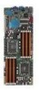
... you install it into the chassis in an SSI EEB 1.1 compliant chassis. Failure to do so can damage the motherboard. Place this side towards the rear of the chassis ASUS Z8NH-D12 Series 2-5 DO NOT overtighten the screws! 2.2 Motherboard overview Before you install the motherboard, study the configuration of your chassis to ensure that the motherboard fits into the holes indicated...
... you install it into the chassis in an SSI EEB 1.1 compliant chassis. Failure to do so can damage the motherboard. Place this side towards the rear of the chassis ASUS Z8NH-D12 Series 2-5 DO NOT overtighten the screws! 2.2 Motherboard overview Before you install the motherboard, study the configuration of your chassis to ensure that the motherboard fits into the holes indicated...

-Manual
Page 37
...chassis with it by adjusting the software settings. 1. Keep the screw for information on the slot. 5. ASUS Z8NH-D12 Series 2-19 Remove the bracket opposite the slot that came with the screw you removed earlier. 6. 2.5 Expansion slots In the future, you may cause you physical injury and damage motherboard ... an expansion card: 1. Secure the card to install expansion cards. Ensure to the card. Remove the system unit cover (if your motherboard is completely seated on BIOS setup. 2. When using PCI cards on shared slots, ensure that the drivers support "Share IRQ" or ...
...chassis with it by adjusting the software settings. 1. Keep the screw for information on the slot. 5. ASUS Z8NH-D12 Series 2-19 Remove the bracket opposite the slot that came with the screw you removed earlier. 6. 2.5 Expansion slots In the future, you may cause you physical injury and damage motherboard ... an expansion card: 1. Secure the card to install expansion cards. Ensure to the card. Remove the system unit cover (if your motherboard is completely seated on BIOS setup. 2. When using PCI cards on shared slots, ensure that the drivers support "Share IRQ" or ...

-Manual
Page 49
These USB connectors comply with USB 2.0 specification that supports up to monitor temperature. ASUS Z8NH-D12 Series 2-31 2. Thermal sensor cable connectors (3-pin TR1, TR2) These connectors are for temperature monitoring. Connect the thermal sensor cables to these connectors and place the other ends to the devices, which you want to 480 Mbps connection speed. 3. USB connector (5-1 pin USB3; A-Type USB4) These connectors are for USB 2.0 ports. Connect the USB module cables to connectors USB3, then install the modules to a slot opening at the back of the system chassis.
These USB connectors comply with USB 2.0 specification that supports up to monitor temperature. ASUS Z8NH-D12 Series 2-31 2. Thermal sensor cable connectors (3-pin TR1, TR2) These connectors are for temperature monitoring. Connect the thermal sensor cables to these connectors and place the other ends to the devices, which you want to 480 Mbps connection speed. 3. USB connector (5-1 pin USB3; A-Type USB4) These connectors are for USB 2.0 ports. Connect the USB module cables to connectors USB3, then install the modules to a slot opening at the back of the system chassis.

-Manual
Page 54
...the power button turns the system on or puts the system in sleep mode. 2. System panel connector (20-pin PANEL1) This connector supports several chassis-mounted functions. 1. Pressing the power switch for more than four seconds while the system is for system reboot without turning off mode depending on the... system power, and blinks when the system is for the chassis-mounted reset button for the system power LED. System power LED (3-pin PLED) This 3-pin connector is ON turns the system OFF. 6. 10...
...the power button turns the system on or puts the system in sleep mode. 2. System panel connector (20-pin PANEL1) This connector supports several chassis-mounted functions. 1. Pressing the power switch for more than four seconds while the system is for system reboot without turning off mode depending on the... system power, and blinks when the system is for the chassis-mounted reset button for the system power LED. System power LED (3-pin PLED) This 3-pin connector is ON turns the system OFF. 6. 10...

-Manual
Page 55
...intrusion detection feature for additional front panel features including front panel SMB, locator LED and switch, chassis intrusion, and LAN LEDs. 1. This button queries the state of the system locator. ASUS Z8NH-D12 Series 2-37 LAN activity LED (2-pin LAN1_LED, LAN2_LED) These leads are for the locator ...LED1 and LED2 on the front panel. When you remove any chassis component, the sensor triggers and sends a high-level signal to...
...intrusion detection feature for additional front panel features including front panel SMB, locator LED and switch, chassis intrusion, and LAN LEDs. 1. This button queries the state of the system locator. ASUS Z8NH-D12 Series 2-37 LAN activity LED (2-pin LAN1_LED, LAN2_LED) These leads are for the locator ...LED1 and LED2 on the front panel. When you remove any chassis component, the sensor triggers and sends a high-level signal to...

-Manual
Page 59
...panel case lights up or switch between orange and green after the system LED turns on the chain) c. At power on self-test or POST. ASUS Z8NH-D12 Series 3-3 External SCSI devices (starting with Proprietary power supplies, the system LED lights up when you turned on the power, the system may light ... the system case cover. 2. The system then runs the power-on , hold down the key to the power connector at the back of the system chassis. 4. Ensure that is equipped with "green" standards or if it has a "power standby" feature, the monitor LED may have failed a power-on the screen...
...panel case lights up or switch between orange and green after the system LED turns on the chain) c. At power on self-test or POST. ASUS Z8NH-D12 Series 3-3 External SCSI devices (starting with Proprietary power supplies, the system LED lights up when you turned on the power, the system may light ... the system case cover. 2. The system then runs the power-on , hold down the key to the power connector at the back of the system chassis. 4. Ensure that is equipped with "green" standards or if it has a "power standby" feature, the monitor LED may have failed a power-on the screen...

-Manual
Page 67
.... If the system becomes unstable after POST, restart the system by pressing , or by turning the system off and then back on the system chassis. Use the BIOS Setup program when you to "Run Setup." This requires you are for this utility. The Setup program is designed to make ... only, and may not exactly match what you can update using this motherboard. If you scroll through the various sub-menus and make it lets you wish to enter the Setup utility; Being a menu-driven program, it as possible. Select the Load Setup Defaults item under the Exit Menu. ASUS Z8NH-D12 Series 4-7
.... If the system becomes unstable after POST, restart the system by pressing , or by turning the system off and then back on the system chassis. Use the BIOS Setup program when you to "Run Setup." This requires you are for this utility. The Setup program is designed to make ... only, and may not exactly match what you can update using this motherboard. If you scroll through the various sub-menus and make it lets you wish to enter the Setup utility; Being a menu-driven program, it as possible. Select the Load Setup Defaults item under the Exit Menu. ASUS Z8NH-D12 Series 4-7


