

User Guide
Page 3
... Operation safety viii Australia statement notice ix How this guide is organized x Where to find more information x Z10PE-D16 Series specifications summary xii Chapter 1: Product Introduction 1.1 Welcome!...1-2 1.2 Package contents 1-2 1.3 Serial number label 1-3 1.4 Special features 1-3 1.4.1 Product highlights 1-3 1.4.2 Innovative ASUS features 1-4 Chapter 2: Hardware Information 2.1 Before you proceed 2-2 2.2 Motherboard overview 2-3 2.2.1 Placement direction 2-3 2.2.2 Screw holes 2-3 2.2.3 Motherboard layout 2-4 2.2.4 Layout...
... Operation safety viii Australia statement notice ix How this guide is organized x Where to find more information x Z10PE-D16 Series specifications summary xii Chapter 1: Product Introduction 1.1 Welcome!...1-2 1.2 Package contents 1-2 1.3 Serial number label 1-3 1.4 Special features 1-3 1.4.1 Product highlights 1-3 1.4.2 Innovative ASUS features 1-4 Chapter 2: Hardware Information 2.1 Before you proceed 2-2 2.2 Motherboard overview 2-3 2.2.1 Placement direction 2-3 2.2.2 Screw holes 2-3 2.2.3 Motherboard layout 2-4 2.2.4 Layout...
User Guide
Page 7
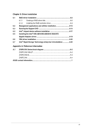
...-AM1/I350-AM2/I210 X540-BT2 Gigabit Adapters driver 6-19 6.6 VGA driver installation 6-22 6.7 Intel® Rapid Storage Technology enterprise 4.0 installation 6-24 Appendix A: Reference Information A.1 Z10PE-D16 Series block diagram A-2 Z10PE-D16/10G-2T A-2 Z10PE-D16/4L A-3 Z10PE-D16 A-4 ASUS contact information 1 vii
...-AM1/I350-AM2/I210 X540-BT2 Gigabit Adapters driver 6-19 6.6 VGA driver installation 6-22 6.7 Intel® Rapid Storage Technology enterprise 4.0 installation 6-24 Appendix A: Reference Information A.1 Z10PE-D16 Series block diagram A-2 Z10PE-D16/10G-2T A-2 Z10PE-D16/4L A-3 Z10PE-D16 A-4 ASUS contact information 1 vii
User Guide
Page 13
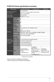
Fan Speed Control ASUS Features Rack Ready (Rack and Pedestal dual use) ASWM Enterprise Total Slots 16 (4 channels per CPU, 2 DIMMs per CPU) Voltage 1.2 V Memory Capacity Maximum up to ... next page) * Maximum at 2133 MT/s at one DIMM per channel (DCP) only. ** Refer to www.asus.com for the complete list of supported CPUs. xiii x 13 in . Z10PE-D16 Series specifications summary Model Name Z10PE-D16/10G-2T Z10PE-D16/4L Z10PE-D16 Processor Support / System Bus 2 x Socket R3 2011 Intel® Xeon® processor E5-2600 V3 product...
Fan Speed Control ASUS Features Rack Ready (Rack and Pedestal dual use) ASWM Enterprise Total Slots 16 (4 channels per CPU, 2 DIMMs per CPU) Voltage 1.2 V Memory Capacity Maximum up to ... next page) * Maximum at 2133 MT/s at one DIMM per channel (DCP) only. ** Refer to www.asus.com for the complete list of supported CPUs. xiii x 13 in . Z10PE-D16 Series specifications summary Model Name Z10PE-D16/10G-2T Z10PE-D16/4L Z10PE-D16 Processor Support / System Bus 2 x Socket R3 2011 Intel® Xeon® processor E5-2600 V3 product...
User Guide
Page 14
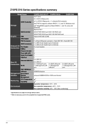
xiv Z10PE-D16 Series specifications summary Model Name Storage SATA Controller SAS Controller Graphic VGA TPM Header PSU Connector USB Connectors Onboard I/O Fan Header Connectors SMBus Chassis Intruder Front ...-2T Z10PE-D16/4L Intel® C612 Z10PE-D16 10 x SATA 6 Gbps ports or 9 x SATA 6 Gbps ports + 1 x discrete M.2 connector Intel® RSTe (supports software RAID 0, 1, 5, and 10, Windows only) LSI® MegaRAID (supports software RAID 0, 1, and 10, Linux and Windows) Optional kits**: ASUS PIKE 3008 8-port SAS 12G RAID card ASUS PIKE 3108 8-port SAS 12G...
xiv Z10PE-D16 Series specifications summary Model Name Storage SATA Controller SAS Controller Graphic VGA TPM Header PSU Connector USB Connectors Onboard I/O Fan Header Connectors SMBus Chassis Intruder Front ...-2T Z10PE-D16/4L Intel® C612 Z10PE-D16 10 x SATA 6 Gbps ports or 9 x SATA 6 Gbps ports + 1 x discrete M.2 connector Intel® RSTe (supports software RAID 0, 1, 5, and 10, Windows only) LSI® MegaRAID (supports software RAID 0, 1, and 10, Linux and Windows) Optional kits**: ASUS PIKE 3008 8-port SAS 12G RAID card ASUS PIKE 3108 8-port SAS 12G...
User Guide
Page 16
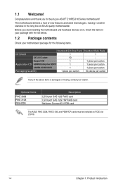
...making it , check the items in the long line of the above items is damaged or missing, contact your motherboard package for buying an ASUS® Z10PE-D16 Series motherboard! Optional items PIKE 3008 PIKE 3108 PEM-FDR Description LSI 8-port SAS 12G RAID card LSI 8-port SAS 12G HW RAID card Mellanox... ConnectX-3 FDR card The ASUS PIKE 3008, PIKE 3108, and PEM-FDR cards must be installed on it another standout in your package with the...
...making it , check the items in the long line of the above items is damaged or missing, contact your motherboard package for buying an ASUS® Z10PE-D16 Series motherboard! Optional items PIKE 3008 PIKE 3108 PEM-FDR Description LSI 8-port SAS 12G RAID card LSI 8-port SAS 12G HW RAID card Mellanox... ConnectX-3 FDR card The ASUS PIKE 3008, PIKE 3108, and PEM-FDR cards must be installed on it another standout in your package with the...

User Guide
Page 17
... processor power management with next-generation processor power management. DDR4 offers a lower voltage standard of up to your problems. Z10PE-D16 Series xxS2xxxxxxxx Made in China 合格 1.4 Special features 1.4.1 Product highlights Latest Processor Technology The motherboard supports Intel Xeon&#.... With the correct serial number of the product, ASUS Technical Support team members can then offer a quicker and satisfying solution to 9.6GT/s. Z10PE-D16 Series 1-3 1.3 Serial number label Before requesting support from the ASUS Technical Support team, you must take note of the...
... processor power management with next-generation processor power management. DDR4 offers a lower voltage standard of up to your problems. Z10PE-D16 Series xxS2xxxxxxxx Made in China 合格 1.4 Special features 1.4.1 Product highlights Latest Processor Technology The motherboard supports Intel Xeon&#.... With the correct serial number of the product, ASUS Technical Support team members can then offer a quicker and satisfying solution to 9.6GT/s. Z10PE-D16 Series 1-3 1.3 Serial number label Before requesting support from the ASUS Technical Support team, you must take note of the...
User Guide
Page 18
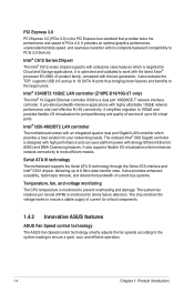
... Series Chipset The Intel® C612 series chipset supports with the last generation, it also reduces the TDP, supports USB 3.0 and up to 64 virtual ports. The system fan rotations per minute (RPM) is monitored for critical components. 1.4.2 Innovative ASUS features ASUS Fan Speed control technology The ASUS...the Serial ATA interface and Intel® C612 chipset, delivering up to PCIe 2.0 devices. Intel® X540BT2 10GbE LAN controller (Z10PE-D16/10G-2T only) The Intel® 10 Gigabit Ethernet controller X540 is designed with high performance and can save platform power with an...
... Series Chipset The Intel® C612 series chipset supports with the last generation, it also reduces the TDP, supports USB 3.0 and up to 64 virtual ports. The system fan rotations per minute (RPM) is monitored for critical components. 1.4.2 Innovative ASUS features ASUS Fan Speed control technology The ASUS...the Serial ATA interface and Intel® C612 chipset, delivering up to PCIe 2.0 devices. Intel® X540BT2 10GbE LAN controller (Z10PE-D16/10G-2T only) The Intel® 10 Gigabit Ethernet controller X540 is designed with high performance and can save platform power with an...

User Guide
Page 21
... in the correct orientation. To optimize the features of your motherboard, we highly recommend that you install the motherboard, study the configuration of the chassis Z10PE-D16 Series 2-3 Ensure to the chassis.
... in the correct orientation. To optimize the features of your motherboard, we highly recommend that you install the motherboard, study the configuration of the chassis Z10PE-D16 Series 2-3 Ensure to the chassis.

User Guide
Page 25
CPU sockets 2. Baseboard Management Controller LED (BMCLED1) 3. BMC Setting (3-pin BMC_EN1) Page 2-26 2-27 2-27 2-28 2-28 2-29 2-29 2-30 Z10PE-D16 Series 2-7 Location LED (LOCLED2) 6. DDR4 thermal event setting (3-pin DIMMTRIP1) 7. DDR4 sockets 3. CATT LED (CATTERR1) 8. Standby Power LED (SBPWR1) 2. CPU Warning LED (ERRCPU1, ERRCPU2) 4. 2.2.4 Layout contents ...
CPU sockets 2. Baseboard Management Controller LED (BMCLED1) 3. BMC Setting (3-pin BMC_EN1) Page 2-26 2-27 2-27 2-28 2-28 2-29 2-29 2-30 Z10PE-D16 Series 2-7 Location LED (LOCLED2) 6. DDR4 thermal event setting (3-pin DIMMTRIP1) 7. DDR4 sockets 3. CATT LED (CATTERR1) 8. Standby Power LED (SBPWR1) 2. CPU Warning LED (ERRCPU1, ERRCPU2) 4. 2.2.4 Layout contents ...

User Guide
Page 27
...your retailer immediately if the PnP cap is missing, or if you and the triangle mark is on the top-right position. Triangle mark Z10PE-D16 Series 2-9 Before installing the CPU, ensure that the PnP cap is shipment/ transit-related. • Keep the cap after installing the motherboard.... socket on the LGA 2011-3 socket. • The product warranty does not cover damage to the PnP cap/socket contacts/motherboard components. ASUS will process Return Merchandise Authorization (RMA) requests only if the motherboard comes with a surface mount LGA 2011-3 socket designed for the Intel&#...
...your retailer immediately if the PnP cap is missing, or if you and the triangle mark is on the top-right position. Triangle mark Z10PE-D16 Series 2-9 Before installing the CPU, ensure that the PnP cap is shipment/ transit-related. • Keep the cap after installing the motherboard.... socket on the LGA 2011-3 socket. • The product warranty does not cover damage to the PnP cap/socket contacts/motherboard components. ASUS will process Return Merchandise Authorization (RMA) requests only if the motherboard comes with a surface mount LGA 2011-3 socket designed for the Intel&#...

User Guide
Page 29
... the CPU over the socket ensuring that the triangle mark on the CPU matches the triangle mark on top of the Load plate 5. 4. Triangle mark Z10PE-D16 Series 2-11 Push the left load lever to close the load plate as it sit on the socket box. 8. Get the CPU. 7. Do not force to...
... the CPU over the socket ensuring that the triangle mark on the CPU matches the triangle mark on top of the Load plate 5. 4. Triangle mark Z10PE-D16 Series 2-11 Push the left load lever to close the load plate as it sit on the socket box. 8. Get the CPU. 7. Do not force to...

User Guide
Page 31
The Thermal Interface Material is spread in contact with pre-applied Thermal Interface Material. Z10PE-D16 Series 2-13 DO NOT forget to the connector on the motherboard labeled CPU_FAN1 / CPU_FAN2. Hardware monitoring errors can occur if you fail to the exposed area ...
The Thermal Interface Material is spread in contact with pre-applied Thermal Interface Material. Z10PE-D16 Series 2-13 DO NOT forget to the connector on the motherboard labeled CPU_FAN1 / CPU_FAN2. Hardware monitoring errors can occur if you fail to the exposed area ...

User Guide
Page 33
... (CPU2) A2 A1 B2 B1 C2 C1 D2 D1 E2 E1 F2 F1 G2 G1 H2 H1 2 DIMMs P P 4 DIMMs P P P P 8 DIMMs P P P P P P P P 12 DIMMs P P P P P PPPPP P P 16 DIMMs P P P P P P P P P P P P P P P P Z10PE-D16 Series 2-15 Single CPU configuration You can refer to the following recommended memory population for a single CPU configuration.
... (CPU2) A2 A1 B2 B1 C2 C1 D2 D1 E2 E1 F2 F1 G2 G1 H2 H1 2 DIMMs P P 4 DIMMs P P P P 8 DIMMs P P P P P P P P 12 DIMMs P P P P P PPPPP P P 16 DIMMs P P P P P P P P P P P P P P P P Z10PE-D16 Series 2-15 Single CPU configuration You can refer to the following recommended memory population for a single CPU configuration.
User Guide
Page 35
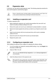
... that the drivers support "Share IRQ" or that they support. When using PCI cards on the system and change the necessary BIOS settings, if any. Z10PE-D16 Series 2-17 Failure to do not need to the chassis with the slot and press firmly until the card is already installed in section Interrupt assignments...
... that the drivers support "Share IRQ" or that they support. When using PCI cards on the system and change the necessary BIOS settings, if any. Z10PE-D16 Series 2-17 Failure to do not need to the chassis with the slot and press firmly until the card is already installed in section Interrupt assignments...

User Guide
Page 39
CPU Warning LED (ERRCPU1, ERRCPU2) The CPU warning LEDs light up when you turn on the system using the Power-on either CPU1, CPU2, or both. 4. Z10PE-D16 Series 2-21 Power LED (P5VLED1) This LED lights up to indicate failure on button. 3.
CPU Warning LED (ERRCPU1, ERRCPU2) The CPU warning LEDs light up when you turn on the system using the Power-on either CPU1, CPU2, or both. 4. Z10PE-D16 Series 2-21 Power LED (P5VLED1) This LED lights up to indicate failure on button. 3.

User Guide
Page 41
Refer to operate. 8. Q-Code LEDs (LED1) The Q-Code LED provides a 2-digit display that the system has experienced a fatal or catastrophic error and cannot continue to the Q-Code table of your system. 7. Z10PE-D16 Series 2-23 CATT LED (CATTERR1) The CATT LED indicates that shows the status of this user guide for more information about the 2-digit codes.
Refer to operate. 8. Q-Code LEDs (LED1) The Q-Code LED provides a 2-digit display that the system has experienced a fatal or catastrophic error and cannot continue to the Q-Code table of your system. 7. Z10PE-D16 Series 2-23 CATT LED (CATTERR1) The CATT LED indicates that shows the status of this user guide for more information about the 2-digit codes.

User Guide
Page 45
... the Gigabit LAN feature. Refer to activate the VGA feature. 3. LAN_SW3, LAN_SW4 for I350-BT2 - Set to pins 1-2 to the table below for I350-AM2; 2. Z10PE-D16 Series 2-27 for X540-BT2 Z10PE-D16/4L Z10PE-D16 for I350-AM2 for X540-BT2 or I350-BT2 LAN controllers.
... the Gigabit LAN feature. Refer to activate the VGA feature. 3. LAN_SW3, LAN_SW4 for I350-BT2 - Set to pins 1-2 to the table below for I350-AM2; 2. Z10PE-D16 Series 2-27 for X540-BT2 Z10PE-D16/4L Z10PE-D16 for I350-AM2 for X540-BT2 or I350-BT2 LAN controllers.

User Guide
Page 47
Z10PE-D16 Series 2-29 Place the jumper caps over pins 1-2 to use the Intel® Rapid Storage Technology enterprise SATA Option ROM Utility. otherwise, place the jumper caps to pins 2-3 to enable or disable DDR4 DIMM thermal sensing event pin. 7. DDR4 thermal event setting (3-pin DIMMTRIP1) This jumper allows you create disk arrays. 6. RAID configuration utility selection (3-pin RAID_SEL1) This jumper allows you to select the RAID configuration utility to use when you to use the third party software LSI MegaRAID software RAID Configuration Utility;
Z10PE-D16 Series 2-29 Place the jumper caps over pins 1-2 to use the Intel® Rapid Storage Technology enterprise SATA Option ROM Utility. otherwise, place the jumper caps to pins 2-3 to enable or disable DDR4 DIMM thermal sensing event pin. 7. DDR4 thermal event setting (3-pin DIMMTRIP1) This jumper allows you create disk arrays. 6. RAID configuration utility selection (3-pin RAID_SEL1) This jumper allows you to select the RAID configuration utility to use when you to use the third party software LSI MegaRAID software RAID Configuration Utility;
User Guide
Page 49
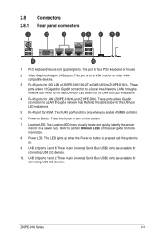
...the system. 7. USB 3.0 ports 1 and 2. 2.8 Connectors 2.8.1 Rear panel connectors 1. Refer to section Onboard LEDs of Z10PE-D16/10G-2T or GbE LAN for iKVM. Power LED. These 4-pin Universal Serial Bus (USB) ports are available for the...10G LAN of this button to the table below for connecting USB 3.0 devices. This port is for LAN (Z10PE-D16/4L and Z10PE-D16). compatible devices. 3. The Location LED helps visually locate and quickly identify the server in error on Button. .... 6. Press this user guide for connecting USB 2.0 devices. 10. Z10PE-D16 Series 2-31
...the system. 7. USB 3.0 ports 1 and 2. 2.8 Connectors 2.8.1 Rear panel connectors 1. Refer to section Onboard LEDs of Z10PE-D16/10G-2T or GbE LAN for iKVM. Power LED. These 4-pin Universal Serial Bus (USB) ports are available for the...10G LAN of this button to the table below for connecting USB 3.0 devices. This port is for LAN (Z10PE-D16/4L and Z10PE-D16). compatible devices. 3. The Location LED helps visually locate and quickly identify the server in error on Button. .... 6. Press this user guide for connecting USB 2.0 devices. 10. Z10PE-D16 Series 2-31

User Guide
Page 51
..., refer to the RAID Configuration chapter of this user guide. • The actual data transfer rate depends on the speed of data transfer rate. Z10PE-D16 Series 2-33 Serial ATA 6.0 Gbps connectors (7-pin SATA1, SATA2, SATA3, SATA4, SATA5, SATA6 [Light Blue], SSATA1, SSATA2, SSATA3 [Gray], SSATA4... [Light Gray]) Supported by the Intel® C612 series Chipset, these connectors are for the Serial ATA signal cables for Serial ATA hard disk drives that allows up to create a RAID 0, RAID 1, RAID...
..., refer to the RAID Configuration chapter of this user guide. • The actual data transfer rate depends on the speed of data transfer rate. Z10PE-D16 Series 2-33 Serial ATA 6.0 Gbps connectors (7-pin SATA1, SATA2, SATA3, SATA4, SATA5, SATA6 [Light Blue], SSATA1, SSATA2, SSATA3 [Gray], SSATA4... [Light Gray]) Supported by the Intel® C612 series Chipset, these connectors are for the Serial ATA signal cables for Serial ATA hard disk drives that allows up to create a RAID 0, RAID 1, RAID...