
User Manual
Page 13
ASUS WS C246M PRO 1-1 Failure to do so may cause severe damage to avoid touching the ICs on them due to static electricity. • Hold components by the edges ...
ASUS WS C246M PRO 1-1 Failure to do so may cause severe damage to avoid touching the ICs on them due to static electricity. • Hold components by the edges ...

User Manual
Page 15
...) Page 1-5 1-23 1-11 1-24 1-25 1-20 1-26 1-19 2-11 1-10 1-16 1-24 1-22 1-21 1-11 1-18 1-19 1-25 1-15 1-18 1-17 1-20 1-17 1-9 1-22 1-8 1-4 1-10 ASUS WS C246M PRO 1-3 M.2 (NGFF) connector (NGFF1) 8. System Management Bus (SMBUS) connector (5-1 pin SMBUS1) 6. TPM connector (14-1 pin TPM1) 22. Chapter 1 Layout contents Connectors/Jumpers/Buttons and switches/Slots...
...) Page 1-5 1-23 1-11 1-24 1-25 1-20 1-26 1-19 2-11 1-10 1-16 1-24 1-22 1-21 1-11 1-18 1-19 1-25 1-15 1-18 1-17 1-20 1-17 1-9 1-22 1-8 1-4 1-10 ASUS WS C246M PRO 1-3 M.2 (NGFF) connector (NGFF1) 8. System Management Bus (SMBUS) connector (5-1 pin SMBUS1) 6. TPM connector (14-1 pin TPM1) 22. Chapter 1 Layout contents Connectors/Jumpers/Buttons and switches/Slots...

User Manual
Page 17
Chapter 1 1.1.4 System memory The motherboard comes with four DDR 4 (Double Data Rate 4) Dual Inline Memory Modules (DIMM) slots. Recommended memory configurations ASUS WS C246M PRO 1-5 A DDR4 module is notched differently from a DDR, DDR2 or DDR3 module. DO NOT install a DDR, DDR2 or DDR3 memory module to the DDR4 slot.
Chapter 1 1.1.4 System memory The motherboard comes with four DDR 4 (Double Data Rate 4) Dual Inline Memory Modules (DIMM) slots. Recommended memory configurations ASUS WS C246M PRO 1-5 A DDR4 module is notched differently from a DDR, DDR2 or DDR3 module. DO NOT install a DDR, DDR2 or DDR3 memory module to the DDR4 slot.

User Manual
Page 19
1.1.5 Expansion slots Unplug the power cord before adding or removing expansion cards. Chapter 1 Slot No. 1 2 3 Slot Description PCIE x1_1 slot PCIE x16_1 slot PCIE x8_1 slot VGA / PCIe configuration PCIe 3.0 x1_1 PCIe 3.0 x16_1 PCIe 3.0 x8_1 PCI Express 3.0 operating mode Single VGA / PCIe card x1 x16 x4 ASUS WS C246M PRO 1-7 Failure to do so may cause you physical injury and damage motherboard components.
1.1.5 Expansion slots Unplug the power cord before adding or removing expansion cards. Chapter 1 Slot No. 1 2 3 Slot Description PCIE x1_1 slot PCIE x16_1 slot PCIE x8_1 slot VGA / PCIe configuration PCIe 3.0 x1_1 PCIe 3.0 x16_1 PCIe 3.0 x8_1 PCI Express 3.0 operating mode Single VGA / PCIe card x1 x16 x4 ASUS WS C246M PRO 1-7 Failure to do so may cause you physical injury and damage motherboard components.

User Manual
Page 21
... the jumper cap from pins 1-2 (default) to clear the Real Time Clock (RTC) RAM in CMOS, which include system setup information such as system passwords. ASUS WS C246M PRO 1-9 Clear RTC RAM (3-pin CLRTC1) This jumper allows you to pins 2-3. The onboard button cell battery powers the RAM data in CMOS. Turn OFF the...
... the jumper cap from pins 1-2 (default) to clear the Real Time Clock (RTC) RAM in CMOS, which include system setup information such as system passwords. ASUS WS C246M PRO 1-9 Clear RTC RAM (3-pin CLRTC1) This jumper allows you to pins 2-3. The onboard button cell battery powers the RAM data in CMOS. Turn OFF the...
User Manual
Page 23
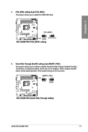
PCH_MFG1 setting (3-pin PCH_MFG1) This jumper allows you to enable or disable the Smart Ride Through (SmaRT) function. This feature is enabled by default. Set to pins 2-3 to update the BIOS ME block. 5. ASUS WS C246M PRO 1-11 When enabled, SmaRT allows uninterrupted operation of the system during an AC loss event. Smart Ride Through (SmaRT) setting (3-pin SMART_PSU1) This jumper allows you to disable it. Chapter 1 4.
PCH_MFG1 setting (3-pin PCH_MFG1) This jumper allows you to enable or disable the Smart Ride Through (SmaRT) function. This feature is enabled by default. Set to pins 2-3 to update the BIOS ME block. 5. ASUS WS C246M PRO 1-11 When enabled, SmaRT allows uninterrupted operation of the system during an AC loss event. Smart Ride Through (SmaRT) setting (3-pin SMART_PSU1) This jumper allows you to disable it. Chapter 1 4.

User Manual
Page 25
Chapter 1 3. ME LED (MELED1) The ME LED is an onboard LED that a CPU error or failure has occurred. 4. CPU Warning LED (ERRCPU1) The CPU warning LED lights up to indicate that blinks when the ME is operating properly. ASUS WS C246M PRO 1-13
Chapter 1 3. ME LED (MELED1) The ME LED is an onboard LED that a CPU error or failure has occurred. 4. CPU Warning LED (ERRCPU1) The CPU warning LED lights up to indicate that blinks when the ME is operating properly. ASUS WS C246M PRO 1-13

User Manual
Page 27
The actual cause may vary from case to case. • Please refer to the Q-Code table in the Appendix section for troubleshooting. ASUS WS C246M PRO 1-15 Q-Code LED The Q-Code LED design provides you with a 2-digit POST code that displays the system status. • The Q-Code LED provides the most probable cause of an error code as a starting point for more details. Chapter 1 7.
The actual cause may vary from case to case. • Please refer to the Q-Code table in the Appendix section for troubleshooting. ASUS WS C246M PRO 1-15 Q-Code LED The Q-Code LED design provides you with a 2-digit POST code that displays the system status. • The Q-Code LED provides the most probable cause of an error code as a starting point for more details. Chapter 1 7.

User Manual
Page 29
... is purchased separately. 2. TPM connector (14-1 pin TPM1) This connector supports a Trusted Platform Module (TPM) system, which securely store keys, digital certificates, passwords and data. ASUS WS C246M PRO 1-17 Chapter 1 We recommend that supports HD Audio. The TPM module is for a chassis-mounted front panel audio I/O module that you connect a high-definition front...
... is purchased separately. 2. TPM connector (14-1 pin TPM1) This connector supports a Trusted Platform Module (TPM) system, which securely store keys, digital certificates, passwords and data. ASUS WS C246M PRO 1-17 Chapter 1 We recommend that supports HD Audio. The TPM module is for a chassis-mounted front panel audio I/O module that you connect a high-definition front...

User Manual
Page 31
... HDLED1) This LED connector is for the storage add-on card cable connected to connect a USB 2.0 module for additional USB 2.0 front or rear panel ports. ASUS WS C246M PRO 1-19 USB 2.0 connectors (10-1 pin USB34, USB78) The 10-1 pin connector allows you to the SATA or SAS add-on card causes the front panel...
... HDLED1) This LED connector is for the storage add-on card cable connected to connect a USB 2.0 module for additional USB 2.0 front or rear panel ports. ASUS WS C246M PRO 1-19 USB 2.0 connectors (10-1 pin USB34, USB78) The 10-1 pin connector allows you to the SATA or SAS add-on card causes the front panel...

User Manual
Page 33
... drive activity LED (2-pin +HDLED) This 2-pin connector is for the chassis-mounted reset button for the chassis-mounted system warning speaker. ASUS WS C246M PRO 1-21 Connect the HDD Activity LED cable to the front message LED. Pressing the power button turns the system on the system power, and... sleep mode. • Message LED (2-pin MLED) This 2-pin connector is for the system power button. This connector is only enabled for WS C246M PRO/SE. • System warning speaker (4-pin SPEAKER) This 4-pin connector is for the HDD Activity LED. Pressing the power switch for more ...
... drive activity LED (2-pin +HDLED) This 2-pin connector is for the chassis-mounted reset button for the chassis-mounted system warning speaker. ASUS WS C246M PRO 1-21 Connect the HDD Activity LED cable to the front message LED. Pressing the power button turns the system on the system power, and... sleep mode. • Message LED (2-pin MLED) This 2-pin connector is for the system power button. This connector is only enabled for WS C246M PRO/SE. • System warning speaker (4-pin SPEAKER) This 4-pin connector is for the HDD Activity LED. Pressing the power switch for more ...

User Manual
Page 35
ASUS WS C246M PRO 1-23 The power supply plugs are for ATX power supply plugs. Ensure to connect the 8-pin power plug. • For a fully configured system, we recommend ...
ASUS WS C246M PRO 1-23 The power supply plugs are for ATX power supply plugs. Ensure to connect the 8-pin power plug. • For a fully configured system, we recommend ...

User Manual
Page 37
... messages to disable the function. 17. Chassis Intrusion (2-pin INTRUSION1) These leads are for the intrusion detection feature for chassis with intrusion sensor or microswitch. ASUS WS C246M PRO 1-25 Chapter 1 16. The default setting is to short the CHASSIS# and the GND pin by a jumper cap to and from devices rather than tripping...
... messages to disable the function. 17. Chassis Intrusion (2-pin INTRUSION1) These leads are for the intrusion detection feature for chassis with intrusion sensor or microswitch. ASUS WS C246M PRO 1-25 Chapter 1 16. The default setting is to short the CHASSIS# and the GND pin by a jumper cap to and from devices rather than tripping...

User Manual
Page 39
...; Ensure that the PnP cap is shipment/ transit-related. • The product warranty does not cover damage to the PnP cap/socket contacts/motherboard components. ASUS will shoulder the cost of repair only if the damage is on the LGA1151 socket. • Upon purchase of the motherboard, ensure that you see... sockets on the socket and the socket contacts are for reference only. DO NOT install a CPU designed for all models. Load lever Chapter 2 Load plate ASUS WS C246M PRO Retention tab Gold triangle mark Alignment key CPU notches Alignment key 2-1
...; Ensure that the PnP cap is shipment/ transit-related. • The product warranty does not cover damage to the PnP cap/socket contacts/motherboard components. ASUS will shoulder the cost of repair only if the damage is on the LGA1151 socket. • Upon purchase of the motherboard, ensure that you see... sockets on the socket and the socket contacts are for reference only. DO NOT install a CPU designed for all models. Load lever Chapter 2 Load plate ASUS WS C246M PRO Retention tab Gold triangle mark Alignment key CPU notches Alignment key 2-1

User Manual
Page 41
2.1.2 Cooling system installation Apply the Thermal Interface Material to the CPU cooling system and CPU before you install the cooling system, if necessary. To install the CPU heatsink and fan assembly Chapter 2 ASUS WS C246M PRO 2-3
2.1.2 Cooling system installation Apply the Thermal Interface Material to the CPU cooling system and CPU before you install the cooling system, if necessary. To install the CPU heatsink and fan assembly Chapter 2 ASUS WS C246M PRO 2-3

User Manual
Page 43
Doing so can damage the motherboard. Chapter 2 DO NOT overtighten the screws! ASUS WS C246M PRO 2-5 Place eight (8) screws into the holes indicated by circles to secure the motherboard to the chassis. 3.
Doing so can damage the motherboard. Chapter 2 DO NOT overtighten the screws! ASUS WS C246M PRO 2-5 Place eight (8) screws into the holes indicated by circles to secure the motherboard to the chassis. 3.

User Manual
Page 45
2.1.5 ATX power connection Chapter 2 Ensure to connect the 8-pin power plug. 2.1.6 SATA device connection OR ASUS WS C246M PRO 2-7
2.1.5 ATX power connection Chapter 2 Ensure to connect the 8-pin power plug. 2.1.6 SATA device connection OR ASUS WS C246M PRO 2-7

User Manual
Page 47
2.1.8 Expansion card installation To install PCIe x16 cards To install PCIe x1 cards Chapter 2 ASUS WS C246M PRO 2-9
2.1.8 Expansion card installation To install PCIe x16 cards To install PCIe x1 cards Chapter 2 ASUS WS C246M PRO 2-9

User Manual
Page 49
... to the USB Flashback port. On your computer. 4. Download the latest BIOS from the support site at www.asus.com/support/ and save it to a USB storage device. • We recommend you to easily update the BIOS without entering a bootable environment, ideal for three seconds to start the update process. ASUS WS C246M PRO 2-11
... to the USB Flashback port. On your computer. 4. Download the latest BIOS from the support site at www.asus.com/support/ and save it to a USB storage device. • We recommend you to easily update the BIOS without entering a bootable environment, ideal for three seconds to start the update process. ASUS WS C246M PRO 2-11

User Manual
Page 51
... 2 devices to USB 3.1 Gen 2 ports for faster and better performance for LAN port LEDs and audio port definitions. USB 3.1 Gen 1 ports 5 and 6 6. USB 2.0 ports 1 and 2 8. ASUS WS C246M PRO 2-13 DisplayPort 2. Audio I /O connection Rear panel connectors 1. Please connect your USB 3.1 Gen 1 devices to USB 3.1 Gen 1 ports and your devices. HDMI port 5.
... 2 devices to USB 3.1 Gen 2 ports for faster and better performance for LAN port LEDs and audio port definitions. USB 3.1 Gen 1 ports 5 and 6 6. USB 2.0 ports 1 and 2 8. ASUS WS C246M PRO 2-13 DisplayPort 2. Audio I /O connection Rear panel connectors 1. Please connect your USB 3.1 Gen 1 devices to USB 3.1 Gen 1 ports and your devices. HDMI port 5.

