
PRIME X299-A Users ManualEnglish
Page 3
Contents Safety information...vi About this guide...vii PRIME X299-A specifications summary ix Package contents...xv Installation tools and components xvi Chapter 1: Product ... Basic Installation 2.1 Building your PC system 2-1 2.1.1 Motherboard installation 2-1 2.1.2 CPU installation 2-3 2.1.3 CPU heatsink and fan assembly installation 2-5 2.1.4 DIMM installation 2-6 2.1.5 ATX power connection 2-7 2.1.6 SATA device connection 2-8 2.1.7 Front I/O connector 2-9 2.1.8 Expansion card installation 2-10 2.1.9 M.2 installation 2-11 2.2 BIOS update utility 2-12 2.3...
Contents Safety information...vi About this guide...vii PRIME X299-A specifications summary ix Package contents...xv Installation tools and components xvi Chapter 1: Product ... Basic Installation 2.1 Building your PC system 2-1 2.1.1 Motherboard installation 2-1 2.1.2 CPU installation 2-3 2.1.3 CPU heatsink and fan assembly installation 2-5 2.1.4 DIMM installation 2-6 2.1.5 ATX power connection 2-7 2.1.6 SATA device connection 2-8 2.1.7 Front I/O connector 2-9 2.1.8 Expansion card installation 2-10 2.1.9 M.2 installation 2-11 2.2 BIOS update utility 2-12 2.3...

PRIME X299-A Users ManualEnglish
Page 14
... EZ Update Anti-virus software (OEM version) Windows® 10 64-bit ATX Form Factor, 12"x 9.6" (30.5 cm x 24.4 cm) • Specifications are subject to change without notice. • Visit the ASUS website for the software manual. PRIME X299-A specifications summary BIOS Features Manageability Support DVD contents Operating system support Form factor 128 Mb...
... EZ Update Anti-virus software (OEM version) Windows® 10 64-bit ATX Form Factor, 12"x 9.6" (30.5 cm x 24.4 cm) • Specifications are subject to change without notice. • Visit the ASUS website for the software manual. PRIME X299-A specifications summary BIOS Features Manageability Support DVD contents Operating system support Form factor 128 Mb...

PRIME X299-A Users ManualEnglish
Page 17
ASUS PRIME X299-A Series 1-1 Chapter 1 Chapter 1: Product Introduction Product Introduction 1 1.1 Motherboard overview 1.1.1 Before you proceed Take note of the following precautions before you install motherboard components or change ... component, ensure that came with the component. • Before you uninstall any component, place it on a grounded antistatic pad or in the bag that the ATX power supply is switched off or the power cord is detached from the power supply. Failure to do so may cause severe damage to avoid...
ASUS PRIME X299-A Series 1-1 Chapter 1 Chapter 1: Product Introduction Product Introduction 1 1.1 Motherboard overview 1.1.1 Before you proceed Take note of the following precautions before you install motherboard components or change ... component, ensure that came with the component. • Before you uninstall any component, place it on a grounded antistatic pad or in the bag that the ATX power supply is switched off or the power cord is detached from the power supply. Failure to do so may cause severe damage to avoid...

PRIME X299-A Users ManualEnglish
Page 19
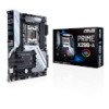
ATX power connectors (24-pin EATXPWR; 8-pin EATX12V_1; 4-pin EATX12V_2) 5. button 7. M.2 sockets (M.2_1(Socket 3); U31G1_34) 11. SATA 6G_65; Power-on button 20. M.2_2(Socket 3)) 8. Thermal sensor ... audio connector (10-1 pin AAFP) Page 1-5 1-21 1-26 1-22 1-4 1-9 1-24 1-18 1-12 1-19 1-25 1-17 1-25 1-11 1-20 1-23 1-12 1-20 1-10 1-13 1-27 1-18 ASUS PRIME X299-A Series 1-3 VROC_HW_KEY connector (4-pin VROC_KEY) 14. Serial port connector (10-1 pin COM) 22. USB 2.0 connector (10-1 pin USB910) 19. SATA 6G_87) 13. MemOK! Clear RTC...
ATX power connectors (24-pin EATXPWR; 8-pin EATX12V_1; 4-pin EATX12V_2) 5. button 7. M.2 sockets (M.2_1(Socket 3); U31G1_34) 11. SATA 6G_65; Power-on button 20. M.2_2(Socket 3)) 8. Thermal sensor ... audio connector (10-1 pin AAFP) Page 1-5 1-21 1-26 1-22 1-4 1-9 1-24 1-18 1-12 1-19 1-25 1-17 1-25 1-11 1-20 1-23 1-12 1-20 1-10 1-13 1-27 1-18 ASUS PRIME X299-A Series 1-3 VROC_HW_KEY connector (4-pin VROC_KEY) 14. Serial port connector (10-1 pin COM) 22. USB 2.0 connector (10-1 pin USB910) 19. SATA 6G_87) 13. MemOK! Clear RTC...

PRIME X299-A Users ManualEnglish
Page 38
...• If you use a PSU with a higher power output when configuring a system with more high-end PCI Express x16 cards, use a PSU with ATX 12V Specification 2.0 (or later version) and provides a minimum power of 350 W. • We recommend that you want to fit these connectors in only ...both the 8-pin and 4-pin power plugs. • For a fully configured system, we recommend that you use two or more power-consuming devices. 8. ATX power connectors (24-pin EATXPWR; 8-pin EATX12V_1; 4-pin EATX12V_2) These connectors are designed to use a power supply unit (PSU) that complies with 1000W ...
...• If you use a PSU with a higher power output when configuring a system with more high-end PCI Express x16 cards, use a PSU with ATX 12V Specification 2.0 (or later version) and provides a minimum power of 350 W. • We recommend that you want to fit these connectors in only ...both the 8-pin and 4-pin power plugs. • For a fully configured system, we recommend that you use two or more power-consuming devices. 8. ATX power connectors (24-pin EATXPWR; 8-pin EATX12V_1; 4-pin EATX12V_2) These connectors are designed to use a power supply unit (PSU) that complies with 1000W ...

PRIME X299-A Users ManualEnglish
Page 39
... warnings. • ATX power button/soft-off button (2-pin PWRSW) This connector is for the HDD Activity LED. Pressing the power button turns the system on or puts the system in sleep mode. • Hard disk drive activity LED (2-pin HDD_LED) This 2-pin connector is removed or replaced. ASUS PRIME X299-A Series 1-23 Connect...
... warnings. • ATX power button/soft-off button (2-pin PWRSW) This connector is for the HDD Activity LED. Pressing the power button turns the system on or puts the system in sleep mode. • Hard disk drive activity LED (2-pin HDD_LED) This 2-pin connector is removed or replaced. ASUS PRIME X299-A Series 1-23 Connect...

PRIME X299-A Users ManualEnglish
Page 42
... in the correct orientation, and the 12V connector is purchased separately. 1-26 Chapter 1: Product Introduction Before you install or remove any component, ensure that the ATX power supply is switched off or the power cord is for RGB LED strips. RGB header (4-pin RGB_HEADER1-2) This connector is detached from the power...
... in the correct orientation, and the 12V connector is purchased separately. 1-26 Chapter 1: Product Introduction Before you install or remove any component, ensure that the ATX power supply is switched off or the power cord is for RGB LED strips. RGB header (4-pin RGB_HEADER1-2) This connector is detached from the power...

PRIME X299-A Users ManualEnglish
Page 51
ASUS PRIME X299-A Series 2-7 2.1.5 ATX power connection Chapter 2 OR AND • DO NOT connect the 4-pin power plug only, the motherboard may overheat under heavy usage. • Ensure to connect the 8-pin power plug, or connect both the 8-pin and 4-pin power plugs.
ASUS PRIME X299-A Series 2-7 2.1.5 ATX power connection Chapter 2 OR AND • DO NOT connect the 4-pin power plug only, the motherboard may overheat under heavy usage. • Ensure to connect the 8-pin power plug, or connect both the 8-pin and 4-pin power plugs.

PRIME X299-A Users ManualEnglish
Page 61
... switch for less than four seconds to put the system on the BIOS setting. ASUS PRIME X299-A Series 2-17 System power 6. If your retailer for the first time 1. Check the jumper settings and connections or call your monitor complies with ATX power supplies, the system LED lights up or change from the time you...with the "green" standards or if it has a "power standby" feature, the monitor LED may have failed a power-on the screen. If you press the ATX power button. While the tests are off the computer While the system is equipped with the last device on self tests (POST).
... switch for less than four seconds to put the system on the BIOS setting. ASUS PRIME X299-A Series 2-17 System power 6. If your retailer for the first time 1. Check the jumper settings and connections or call your monitor complies with ATX power supplies, the system LED lights up or change from the time you...with the "green" standards or if it has a "power standby" feature, the monitor LED may have failed a power-on the screen. If you press the ATX power button. While the tests are off the computer While the system is equipped with the last device on self tests (POST).


