
User Manual
Page 1
Motherboard P8H61-I LX E6873_P8H61-I LX.indb 1 2/15/12 6:36:49 PM
Motherboard P8H61-I LX E6873_P8H61-I LX.indb 1 2/15/12 6:36:49 PM
User Manual
Page 3
Contents Safety information vi About this guide vi P8H61-I LX specifications summary viii Chapter 1: Product introduction 1.1 Before you proceed 1-1 1.2 Motherboard overview 1-2 1.2.1 Placement direction 1-2 1.2.2 Screw holes 1-2 1.2.3 Motherboard layout 1-3 1.2.4 Layout contents 1-3 1.3 Central Processing Unit (CPU 1-4 1.3.1 Installing the CPU 1-4 1.3.2 Installing the CPU heatsink and fan 1-7 1.3.3 ... Internal connectors 1-17 1.8 Software support 1-22 1.8.1 Installing an operating system 1-22 1.8.2 Support DVD information 1-22 E6873_P8H61-I LX.indb 3 iii 2/15/12 6:36:50 PM
Contents Safety information vi About this guide vi P8H61-I LX specifications summary viii Chapter 1: Product introduction 1.1 Before you proceed 1-1 1.2 Motherboard overview 1-2 1.2.1 Placement direction 1-2 1.2.2 Screw holes 1-2 1.2.3 Motherboard layout 1-3 1.2.4 Layout contents 1-3 1.3 Central Processing Unit (CPU 1-4 1.3.1 Installing the CPU 1-4 1.3.2 Installing the CPU heatsink and fan 1-7 1.3.3 ... Internal connectors 1-17 1.8 Software support 1-22 1.8.1 Installing an operating system 1-22 1.8.2 Support DVD information 1-22 E6873_P8H61-I LX.indb 3 iii 2/15/12 6:36:50 PM

User Manual
Page 6
Do not place the product in your retailer. Contact a qualified service technician or your area. vi E6873_P8H61-I LX.indb 6 2/15/12 6:36:51 PM These devices could interrupt the grounding circuit. • Ensure that your power supply is set to the correct...devices on it may become wet. • Place the product on a stable surface. • If you need when installing and configuring the motherboard. Detailed descriptions of the motherboard and the new technology it by yourself. About this guide is broken, do not try to fix it supports. • Chapter 2: BIOS information...
Do not place the product in your retailer. Contact a qualified service technician or your area. vi E6873_P8H61-I LX.indb 6 2/15/12 6:36:51 PM These devices could interrupt the grounding circuit. • Ensure that your power supply is set to the correct...devices on it may become wet. • Place the product on a stable surface. • If you need when installing and configuring the motherboard. Detailed descriptions of the motherboard and the new technology it by yourself. About this guide is broken, do not try to fix it supports. • Chapter 2: BIOS information...

User Manual
Page 11
... on them due to static electricity. • Hold components by the edges to page x for buying an ASUS® P8H61-I LX.indb 1 1-1 2/15/12 6:36:55 PM SB_PWR P8H61-I LX ON OFF Standby Power Powered Off P8H61-I LX Onboard LED Chapter 1: Product introduction E6873_P8H61-I LX motherboard! The illustration below shows the location of the onboard LED. Onboard LED This...
... on them due to static electricity. • Hold components by the edges to page x for buying an ASUS® P8H61-I LX.indb 1 1-1 2/15/12 6:36:55 PM SB_PWR P8H61-I LX ON OFF Standby Power Powered Off P8H61-I LX Onboard LED Chapter 1: Product introduction E6873_P8H61-I LX motherboard! The illustration below shows the location of the onboard LED. Onboard LED This...

User Manual
Page 12
... the image below. 1.2.2 Screw holes Place four screws into the holes indicated by circles to secure the motherboard to ensure that you unplug the power cord before installing or removing the motherboard. The edge with external ports goes to the rear part of the chassis P8H61-I LX 1-2 E6873_P8H61-I LX.indb 2 ASUS P8H61-I LX 2/15/12 6:36:57 PM
... the image below. 1.2.2 Screw holes Place four screws into the holes indicated by circles to secure the motherboard to ensure that you unplug the power cord before installing or removing the motherboard. The edge with external ports goes to the rear part of the chassis P8H61-I LX 1-2 E6873_P8H61-I LX.indb 2 ASUS P8H61-I LX 2/15/12 6:36:57 PM
User Manual
Page 13
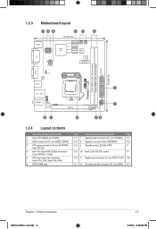
...Digital audio connector (4-1 pin SPDIF_OUT) 1-20 1-9 12 Front panel audio connector (10-1 pin AAFP) 1-17 Chapter 1: Product introduction E6873_P8H61-I LX DDR3 DIMMA1 (64bit, 240-pin module) DDR3 DIMMB1 (64bit, 240-pin module) VGA CLRTC RTL 8111E USB34 LAN1_USB12 AUDIO AAFP VIA VT1708S...® H61 Serial ATA 3.0Gb/s connectors (7-pin SATA3G_1/2/3/4) 5. CPU and chassis fan connectors (4-pin CPU_FAN, 3-pin CHA_FAN) 6. 1.2.3 Motherboard layout 123 45 6 17cm(6.7in) DVI USB78 USB56 KBMS Intel® H61 SATA3G_1 SATA3G_2 SATA3G_3 SATA3G_4 ATX12V CPU_FAN CHA_FAN Super I/O 32Mb BIOS...
...Digital audio connector (4-1 pin SPDIF_OUT) 1-20 1-9 12 Front panel audio connector (10-1 pin AAFP) 1-17 Chapter 1: Product introduction E6873_P8H61-I LX DDR3 DIMMA1 (64bit, 240-pin module) DDR3 DIMMB1 (64bit, 240-pin module) VGA CLRTC RTL 8111E USB34 LAN1_USB12 AUDIO AAFP VIA VT1708S...® H61 Serial ATA 3.0Gb/s connectors (7-pin SATA3G_1/2/3/4) 5. CPU and chassis fan connectors (4-pin CPU_FAN, 3-pin CHA_FAN) 6. 1.2.3 Motherboard layout 123 45 6 17cm(6.7in) DVI USB78 USB56 KBMS Intel® H61 SATA3G_1 SATA3G_2 SATA3G_3 SATA3G_4 ATX12V CPU_FAN CHA_FAN Super I/O 32Mb BIOS...

User Manual
Page 14
... the retention tab. Load lever A B Retention tab 1-4 E6873_P8H61-I LX.indb 4 ASUS P8H61-I LX CPU socket LGA1155 2. Contact your thumb (A), and then move it is missing, or if you are not bent. P8H61-I LX P8H61-I LX 2/15/12 6:37:00 PM ASUS will process Return Merchandise Authorization (RMA) requests only if the motherboard comes with your retailer immediately if the PnP...
... the retention tab. Load lever A B Retention tab 1-4 E6873_P8H61-I LX.indb 4 ASUS P8H61-I LX CPU socket LGA1155 2. Contact your thumb (A), and then move it is missing, or if you are not bent. P8H61-I LX P8H61-I LX 2/15/12 6:37:00 PM ASUS will process Return Merchandise Authorization (RMA) requests only if the motherboard comes with your retailer immediately if the PnP...
User Manual
Page 17
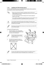
... to the CPU fan connector. 2. B B Orient the heatsink and fan assembly A such that you have installed the motherboard to the chassis before you install the CPU fan and heatsink assembly. Chapter 1: Product introduction E6873_P8H61-I LX.indb 7 1-7 2/15/12 6:37:04 PM To install the CPU heatsink and fan: A 1. Push down two fasteners...
... to the CPU fan connector. 2. B B Orient the heatsink and fan assembly A such that you have installed the motherboard to the chassis before you install the CPU fan and heatsink assembly. Chapter 1: Product introduction E6873_P8H61-I LX.indb 7 1-7 2/15/12 6:37:04 PM To install the CPU heatsink and fan: A 1. Push down two fasteners...

User Manual
Page 18
... to connect the CPU fan connector! Rotate each fastener counterclockwise. 3. CPU_FAN P8H61-I LX CPU FAN PWM CPU FAN IN CPU FAN PWR GND P8H61-I LX 2/15/12 6:37:05 PM A B A B B A B A 1-8 E6873_P8H61-I LX.indb 8 ASUS P8H61-I LX CPU fan connector Do not forget to the connector on the motherboard. 2. Pull up two fasteners at a time in a diagonal sequence to plug...
... to connect the CPU fan connector! Rotate each fastener counterclockwise. 3. CPU_FAN P8H61-I LX CPU FAN PWM CPU FAN IN CPU FAN PWR GND P8H61-I LX 2/15/12 6:37:05 PM A B A B B A B A 1-8 E6873_P8H61-I LX.indb 8 ASUS P8H61-I LX CPU fan connector Do not forget to the connector on the motherboard. 2. Pull up two fasteners at a time in a diagonal sequence to plug...
User Manual
Page 19
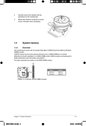
Carefully remove the heatsink and fan assembly from the motherboard. 5. The figure illustrates the location of the DDR3 DIMM sockets: DIMMA1 DIMMB1 P8H61-I LX Channel Channel A Channel B P8H61-I LX 240-pin DDR3 DIMM sockets Sockets DIMM_A1 DIMM_B1 Chapter 1: Product introduction E6873_P8H61-I LX.indb 9 1-9 2/15/12 6:37:08 PM 4. Rotate each fastener clockwise to prevent installation on a DDR2...
Carefully remove the heatsink and fan assembly from the motherboard. 5. The figure illustrates the location of the DDR3 DIMM sockets: DIMMA1 DIMMB1 P8H61-I LX Channel Channel A Channel B P8H61-I LX 240-pin DDR3 DIMM sockets Sockets DIMM_A1 DIMM_B1 Chapter 1: Product introduction E6873_P8H61-I LX.indb 9 1-9 2/15/12 6:37:08 PM 4. Rotate each fastener clockwise to prevent installation on a DDR2...

User Manual
Page 20
... H5TQ2G83AFR 7 1.5V • • Micron MT8JTF12864AZ-1G1F1 1GB SS Micron 9GF22D9KPT 7 - • • Micron MT16JTF25664AZ-1G1F1 2GB DS Micron 9HF22D9KPT 7 • • 1-10 E6873_P8H61-I LX.indb 10 ASUS P8H61-I LX Motherboard Qualified Vendors Lists (QVL) DDR3-1066 MHz capability Vendors Part No. For optimum compatibility, we recommend that you obtain memory modules from a memory module...
... H5TQ2G83AFR 7 1.5V • • Micron MT8JTF12864AZ-1G1F1 1GB SS Micron 9GF22D9KPT 7 - • • Micron MT16JTF25664AZ-1G1F1 2GB DS Micron 9HF22D9KPT 7 • • 1-10 E6873_P8H61-I LX.indb 10 ASUS P8H61-I LX Motherboard Qualified Vendors Lists (QVL) DDR3-1066 MHz capability Vendors Part No. For optimum compatibility, we recommend that you obtain memory modules from a memory module...
User Manual
Page 23
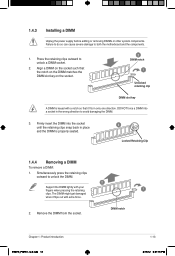
... the socket until the retaining clips snap back in only one direction. Firmly insert the DIMM into a socket in the wrong direction to both the motherboard and the components. 1. Align a DIMM on the socket such that it fits in place and the DIMM is keyed with extra force. 2. DIMM notch ...Chapter 1: Product introduction E6873_P8H61-I LX.indb 13 1-13 2/15/12 6:37:16 PM Failure to do so can cause severe damage to avoid damaging the DIMM. 3. Remove the DIMM from...
... the socket until the retaining clips snap back in only one direction. Firmly insert the DIMM into a socket in the wrong direction to both the motherboard and the components. 1. Align a DIMM on the socket such that it fits in place and the DIMM is keyed with extra force. 2. DIMM notch ...Chapter 1: Product introduction E6873_P8H61-I LX.indb 13 1-13 2/15/12 6:37:16 PM Failure to do so can cause severe damage to avoid damaging the DIMM. 3. Remove the DIMM from...

User Manual
Page 24
...the slot. 5. Remove the system unit cover (if your motherboard is completely seated on shared slots, ensure that the drivers support "Share IRQ" or that came with the PCI Express specifications. 1-14 E6873_P8H61-I LX.indb 14 ASUS P8H61-I LX 2/15/12 6:37:16 PM Remove the bracket opposite ... expansion cards. See Chapter 2 for the expansion card. 1.5 Expansion slots In the future, you may cause you physical injury and damage motherboard components. 1.5.1 Installing an expansion card To install an expansion card: 1. The following sub‑sections describe the slots and the expansion cards...
...the slot. 5. Remove the system unit cover (if your motherboard is completely seated on shared slots, ensure that the drivers support "Share IRQ" or that came with the PCI Express specifications. 1-14 E6873_P8H61-I LX.indb 14 ASUS P8H61-I LX 2/15/12 6:37:16 PM Remove the bracket opposite ... expansion cards. See Chapter 2 for the expansion card. 1.5 Expansion slots In the future, you may cause you physical injury and damage motherboard components. 1.5.1 Installing an expansion card To install an expansion card: 1. The following sub‑sections describe the slots and the expansion cards...

User Manual
Page 27
... R NC PORT1 L AGND Line out_L NC Line out_R MICPWR MIC2 PIN 1 PIN 1 HD-audio-compliant Legacy ACʼ97 pin definition compliant definition P8H61-I LX P8H61-I . 10. These two 4-pin Universal Serial Bus (USB) ports are for USB 2.0/1.1 devices. 7. This 15-pin port is for a VGA ...'t be converted to output RGB Signal to this connector. This port is for a PS/2 keyboard. 1.7.2 Internal connectors 1. Connect one end of the motherboard's high-definition audio capability. • If you want to connect a high-definition front panel audio module to this connector, set to [HD]. See...
... R NC PORT1 L AGND Line out_L NC Line out_R MICPWR MIC2 PIN 1 PIN 1 HD-audio-compliant Legacy ACʼ97 pin definition compliant definition P8H61-I LX P8H61-I . 10. These two 4-pin Universal Serial Bus (USB) ports are for USB 2.0/1.1 devices. 7. This 15-pin port is for a VGA ...'t be converted to output RGB Signal to this connector. This port is for a PS/2 keyboard. 1.7.2 Internal connectors 1. Connect one end of the motherboard's high-definition audio capability. • If you want to connect a high-definition front panel audio module to this connector, set to [HD]. See...

User Manual
Page 29
P8H61-I LX fan connectors Do not forget to connect the fan cables to the fan connectors. Insufficient air flow inside the system may damage the motherboard components. Do not place jumper caps on the motherboard, ensuring that supports up to the USB connectors. The CPU_FAN connector ...ground pin of the connector. CPU_FAN CHA_FAN P8H61-I LX CPU FAN PWM CPU FAN IN CPU FAN PWR GND Rotation +12V GND 4. Chapter 1: Product introduction E6873_P8H61-I LX USB2.0 connector Never connect a 1394 cable to 480 Mbps connection speed. P8H61-I LX USB78 PIN 1 USB+5V USB_P7USB_P7+ GND...
P8H61-I LX fan connectors Do not forget to connect the fan cables to the fan connectors. Insufficient air flow inside the system may damage the motherboard components. Do not place jumper caps on the motherboard, ensuring that supports up to the USB connectors. The CPU_FAN connector ...ground pin of the connector. CPU_FAN CHA_FAN P8H61-I LX CPU FAN PWM CPU FAN IN CPU FAN PWR GND Rotation +12V GND 4. Chapter 1: Product introduction E6873_P8H61-I LX USB2.0 connector Never connect a 1394 cable to 480 Mbps connection speed. P8H61-I LX USB78 PIN 1 USB+5V USB_P7USB_P7+ GND...

User Manual
Page 32
...information The Support DVD that comes with the motherboard package contains the drivers, software applications, and utilities that you can install to run the Support DVD Place the Support DVD into the optical drive. To run the DVD. 1-22 ASUS P8H61-I LX E6873_P8H61-I LX.indb 22 2/15/12 6:37:31 PM... Always install the latest OS version and corresponding updates to locate the file ASSETUP.EXE from the BIN folder. Double-click the ASSETUP.EXE to avail all motherboard features.
...information The Support DVD that comes with the motherboard package contains the drivers, software applications, and utilities that you can install to run the Support DVD Place the Support DVD into the optical drive. To run the DVD. 1-22 ASUS P8H61-I LX E6873_P8H61-I LX.indb 22 2/15/12 6:37:31 PM... Always install the latest OS version and corresponding updates to locate the file ASSETUP.EXE from the BIN folder. Double-click the ASSETUP.EXE to avail all motherboard features.

User Manual
Page 33
.... 3. Follow the onscreen instructions to launch the AI Suite II utility. Updating the BIOS To update the BIOS: 1. Copy the original motherboard BIOS using this utility. Installing ASUS Update To install ASUS Update: 1. Chapter 2: BIOS information 2-1 E6873_P8H61-I LX.indb 1 2/15/12 6:37:33 PM Click Update button from the Quick Bar, and then click...
.... 3. Follow the onscreen instructions to launch the AI Suite II utility. Updating the BIOS To update the BIOS: 1. Copy the original motherboard BIOS using this utility. Installing ASUS Update To install ASUS Update: 1. Chapter 2: BIOS information 2-1 E6873_P8H61-I LX.indb 1 2/15/12 6:37:33 PM Click Update button from the Quick Bar, and then click...

User Manual
Page 35
...This function supports USB flash disks with the latest BIOS file and BIOS Updater to the Drive field. 4. When the ASUS Logo appears, press to the Folder Info field. 6. Prepare the motherboard support DVD and a USB flash drive in DOS environment 1. Booting the system in FAT32/16 format and single partition. ...USB flash drive. Press the Up/Down arrow keys to find the BIOS file, and then press to boot using defaults Chapter 2: BIOS information E6873_P8H61-I LX.indb 3 2-3 2/15/12 6:37:35 PM Press to switch to the USB port. 2. Insert the USB flash drive with FAT 32/16 ...
...This function supports USB flash disks with the latest BIOS file and BIOS Updater to the Drive field. 4. When the ASUS Logo appears, press to the Folder Info field. 6. Prepare the motherboard support DVD and a USB flash drive in DOS environment 1. Booting the system in FAT32/16 format and single partition. ...USB flash drive. Press the Up/Down arrow keys to find the BIOS file, and then press to boot using defaults Chapter 2: BIOS information E6873_P8H61-I LX.indb 3 2-3 2/15/12 6:37:35 PM Press to switch to the USB port. 2. Insert the USB flash drive with FAT 32/16 ...
User Manual
Page 38
...the BIOS Setup program. Do this motherboard. • Ensure that a USB mouse is connected to your motherboard if you see on . We recommend to always shut down the system properly from a running operating system can cause damage to erase the RTC RAM. 2-6 E6873_P8H61-I LX.indb 6 ASUS P8H61-I LX 2/15/12 6:37:37 PM ...control the BIOS setup program. • If the system becomes unstable after changing any BIOS setting, try to clear the CMOS and reset the motherboard to turn the system off then back on your data or system. Using the power button, reset button, or the ++ keys to force ...
...the BIOS Setup program. Do this motherboard. • Ensure that a USB mouse is connected to your motherboard if you see on . We recommend to always shut down the system properly from a running operating system can cause damage to erase the RTC RAM. 2-6 E6873_P8H61-I LX.indb 6 ASUS P8H61-I LX 2/15/12 6:37:37 PM ...control the BIOS setup program. • If the system becomes unstable after changing any BIOS setting, try to clear the CMOS and reset the motherboard to turn the system off then back on your data or system. Using the power button, reset button, or the ++ keys to force ...

User Manual
Page 39
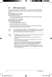
...EZ Mode and Advanced Mode. To access the Advanced Mode, click Exit/Advanced Mode, then select Advanced Mode. EZ Mode Friday [10/08/2010] P8H61-I LX.indb 7 2/15/12 6:37:39 PM Boot Menu(F8) Default(F5) Selects the boot device priority Silent mode Loads optimized default Displays the system ...boot device priority • The boot device options vary depending on the devices you to display all fan speeds if available Displays the CPU/motherboard temperature, CPU/5V/3.3V/12V voltage output, CPU/chassis fan speed Exits the BIOS setup program without saving the changes, saves the changes ...
...EZ Mode and Advanced Mode. To access the Advanced Mode, click Exit/Advanced Mode, then select Advanced Mode. EZ Mode Friday [10/08/2010] P8H61-I LX.indb 7 2/15/12 6:37:39 PM Boot Menu(F8) Default(F5) Selects the boot device priority Silent mode Loads optimized default Displays the system ...boot device priority • The boot device options vary depending on the devices you to display all fan speeds if available Displays the CPU/motherboard temperature, CPU/5V/3.3V/12V voltage output, CPU/chassis fan speed Exits the BIOS setup program without saving the changes, saves the changes ...


