
Motherboard Installation Guide
Page 2
User Guide VT1708A VIA HD Audio Adeck For Windows 2000, Windows XP & Server 2003 Revision History Rev 1.1e Date Jun.13.07 Initial PW Note Initial public release
User Guide VT1708A VIA HD Audio Adeck For Windows 2000, Windows XP & Server 2003 Revision History Rev 1.1e Date Jun.13.07 Initial PW Note Initial public release
Motherboard Installation Guide
Page 3
User Guide VT1708A VIA HD Audio Adeck For Windows 2000, Windows XP & Server 2003 Table of Contents Revision History...2 Table of Contents ...3 List of Figures...4 Introduction ...5 System Requirement ...6 Display Mode ...7 Simple Mode ...7 Full Mode...8 Panel Detail ...9 Top Panel ...9 Bottom Panel...10 Configuration Panels ...11 Speaker Configuration Panel 11 Mixer Configuration Panel 13 Effects Configuration Panel 16 Jack Configuration Panel 18 S/PDIF Configuration Panel 21 System Information Panel 22 Tool Tips ...24 Task Bar ...25 Magic 5.1 ...26
User Guide VT1708A VIA HD Audio Adeck For Windows 2000, Windows XP & Server 2003 Table of Contents Revision History...2 Table of Contents ...3 List of Figures...4 Introduction ...5 System Requirement ...6 Display Mode ...7 Simple Mode ...7 Full Mode...8 Panel Detail ...9 Top Panel ...9 Bottom Panel...10 Configuration Panels ...11 Speaker Configuration Panel 11 Mixer Configuration Panel 13 Effects Configuration Panel 16 Jack Configuration Panel 18 S/PDIF Configuration Panel 21 System Information Panel 22 Tool Tips ...24 Task Bar ...25 Magic 5.1 ...26
Motherboard Installation Guide
Page 4
User Guide VT1708A VIA HD Audio Adeck For Windows 2000, Windows XP & Server 2003 List of Figures Figure 1 - Top Panel ...9 Figure 4 - Mixer Configuration Panel - Equalizer Setting with Smooth Slider Enabled 16 Figure 14 - Equalizer Setting with Smooth Slider Disabled 16 Figure 13 - Front Panel 18 Figure 17 - S/PDIF Out 21 Figure 20 - S/PDIF Configuration Panel - Switching to 4 Channel 26 Figure 28 - Speaker Configuration Panel with Hot Key 23 Figure 24 - Equalizer 16 Figure 12 - Jack Detect Event Occur 19 Figure 18 - S/PDIF Configuration Panel ...
User Guide VT1708A VIA HD Audio Adeck For Windows 2000, Windows XP & Server 2003 List of Figures Figure 1 - Top Panel ...9 Figure 4 - Mixer Configuration Panel - Equalizer Setting with Smooth Slider Enabled 16 Figure 14 - Equalizer Setting with Smooth Slider Disabled 16 Figure 13 - Front Panel 18 Figure 17 - S/PDIF Out 21 Figure 20 - S/PDIF Configuration Panel - Switching to 4 Channel 26 Figure 28 - Speaker Configuration Panel with Hot Key 23 Figure 24 - Equalizer 16 Figure 12 - Jack Detect Event Occur 19 Figure 18 - S/PDIF Configuration Panel ...
Motherboard Installation Guide
Page 5
The main features of Adeck include: Supports various sound enhancement settings with the VIA HD Audio driver and the VIA HD Audio chip. With the advanced audio control interface, users can make the best use of the VIA Audio chip and create powerful customized sound environments. User Guide VT1708A VIA HD Audio Adeck For Windows 2000, Windows XP & Server 2003 5 Introduction Audio Deck (Adeck) is a Windows based program which co-works with detailed user customization Supports active jack detection Supports jack Function configuration Supports configurations for independent headphone and re-...
The main features of Adeck include: Supports various sound enhancement settings with the VIA HD Audio driver and the VIA HD Audio chip. With the advanced audio control interface, users can make the best use of the VIA Audio chip and create powerful customized sound environments. User Guide VT1708A VIA HD Audio Adeck For Windows 2000, Windows XP & Server 2003 5 Introduction Audio Deck (Adeck) is a Windows based program which co-works with detailed user customization Supports active jack detection Supports jack Function configuration Supports configurations for independent headphone and re-...
Motherboard Installation Guide
Page 6
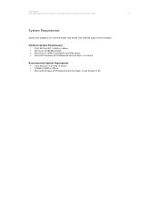
User Guide VT1708A VIA HD Audio Adeck For Windows 2000, Windows XP & Server 2003 6 System Requirement Adeck only supports the VIA HD audio chip series with DirectX 9.0C Minimum System Requirement Intel Pentium III 1.0GHz or above Minimum of 256MB of RAM Minimum of 10MB of available hard disk space Microsoft Windows XP Professional Service Pack 1 or above Recommended System Requirement Intel Pentium 4 2.0GHz or above 512MB of RAM or above Microsoft Window XP Professional Service Pack 2 with VIA HD audio driver installed.
User Guide VT1708A VIA HD Audio Adeck For Windows 2000, Windows XP & Server 2003 6 System Requirement Adeck only supports the VIA HD audio chip series with DirectX 9.0C Minimum System Requirement Intel Pentium III 1.0GHz or above Minimum of 256MB of RAM Minimum of 10MB of available hard disk space Microsoft Windows XP Professional Service Pack 1 or above Recommended System Requirement Intel Pentium 4 2.0GHz or above 512MB of RAM or above Microsoft Window XP Professional Service Pack 2 with VIA HD audio driver installed.
Motherboard Installation Guide
Page 7
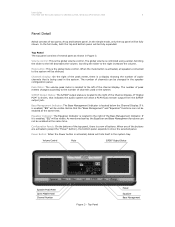
These buttons are activated, the Adeck system will be displayed in detail, he can simply click on the lower part of the buttons are labeled: Speaker, Mixer, Effect, Jack, S/PDIF and Info. To exit Adeck, the user can click on the buttons located on the Power button. Figure 1 - Simple Mode Adeck If the user needs to control the sound effects in the center of channels, S/PDIF out status or sound effect status, etc. The Adeck system is initialized using the simple mode (see Figure 1). In this mode, the user only has limited control and audio information. The basic audio ...
These buttons are activated, the Adeck system will be displayed in detail, he can simply click on the lower part of the buttons are labeled: Speaker, Mixer, Effect, Jack, S/PDIF and Info. To exit Adeck, the user can click on the buttons located on the Power button. Figure 1 - Simple Mode Adeck If the user needs to control the sound effects in the center of channels, S/PDIF out status or sound effect status, etc. The Adeck system is initialized using the simple mode (see Figure 1). In this mode, the user only has limited control and audio information. The basic audio ...
Motherboard Installation Guide
Page 8
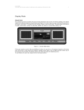
Depending upon the button that was selected, different panels will be displayed in Full Mode. Full Mode Adeck Figure 2 shows an example of Adeck expands. Figure 2 - User Guide VT1708A VIA HD Audio Adeck For Windows 2000, Windows XP & Server 2003 8 Full Mode In the full mode, the bottom part of Adeck in the expanded portion.
Depending upon the button that was selected, different panels will be displayed in Full Mode. Full Mode Adeck Figure 2 shows an example of Adeck expands. Figure 2 - User Guide VT1708A VIA HD Audio Adeck For Windows 2000, Windows XP & Server 2003 8 Full Mode In the full mode, the bottom part of Adeck in the expanded portion.
Motherboard Installation Guide
Page 9
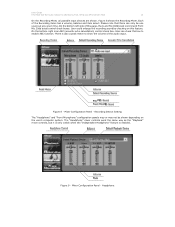
Scrolling the slider to the number of channels used in the system. Channels Display: On the right of the peak meter, there is a display showing the number of peak meters changes according to the right increases the volume. If "Digital PCM" is being used in the system tray. Power Button: When the Power button is the global mute control. In the simple mode, only the top panel will hide itself in the system. Mute button: This is activated, Adeck will be enabled at the same time. The number of audio channels that is shown, that the "Bass Management" and "Equalizer...
Scrolling the slider to the number of channels used in the system. Channels Display: On the right of the peak meter, there is a display showing the number of peak meters changes according to the right increases the volume. If "Digital PCM" is being used in the system tray. Power Button: When the Power button is the global mute control. In the simple mode, only the top panel will hide itself in the system. Mute button: This is activated, Adeck will be enabled at the same time. The number of audio channels that is shown, that the "Bass Management" and "Equalizer...
Motherboard Installation Guide
Page 10
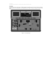
The contents of the Top Panel. To test all speakers, just click the Test button. S/PDIF Configuration Panel: As Figure 19 shows, the user can program the hot keys. Mixer Configuration Panel: As Figure 7 shows, it . Effects Configuration Panel: As Figure 11 shows, there are dependent upon the button that can still be active. Even if the Bottom Panel is already expanded, the contents can be selected: "Equalizer" or "Bass Management". To test a speaker to it contains the basic Playback Mixer and Recording Mixer volume controls. Additionally, the user can configure the S/PDIF ...
The contents of the Top Panel. To test all speakers, just click the Test button. S/PDIF Configuration Panel: As Figure 19 shows, the user can program the hot keys. Mixer Configuration Panel: As Figure 7 shows, it . Effects Configuration Panel: As Figure 11 shows, there are dependent upon the button that can still be active. Even if the Bottom Panel is already expanded, the contents can be selected: "Equalizer" or "Bass Management". To test a speaker to it contains the basic Playback Mixer and Recording Mixer volume controls. Additionally, the user can configure the S/PDIF ...
Motherboard Installation Guide
Page 11
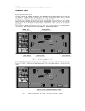
Speaker positions can adjust the volume level for Center/LFE Swapping. Below side of the speaker configuration on the right side, there is a check box for each speaker separately. To control the headphone volume, click on the speaker to hear the test audio clip. There are up to 8 channels available. On the right side of channels will change accordingly. On the left side, the user can test all the speakers accordingly. Speaker Configuration Panel If the "Independent Headphone" feature has been enabled, the maximum number of Speaker Configuration Panel, the user can also be...
Speaker positions can adjust the volume level for Center/LFE Swapping. Below side of the speaker configuration on the right side, there is a check box for each speaker separately. To control the headphone volume, click on the speaker to hear the test audio clip. There are up to 8 channels available. On the right side of channels will change accordingly. On the left side, the user can test all the speakers accordingly. Speaker Configuration Panel If the "Independent Headphone" feature has been enabled, the maximum number of Speaker Configuration Panel, the user can also be...
Motherboard Installation Guide
Page 12
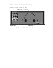
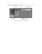
User Guide VT1708A VIA HD Audio Adeck For Windows 2000, Windows XP & Server 2003 12 The headphone volume controls are as shown in Speaker Control Panel Headphone Volume Setting in Figure 6. To switch back to speaker control Headphone Volume Headphone Test Figure 6 - Click here to return to the speaker volume controls, click on the speaker icon at the bottom-right corner.
User Guide VT1708A VIA HD Audio Adeck For Windows 2000, Windows XP & Server 2003 12 The headphone volume controls are as shown in Speaker Control Panel Headphone Volume Setting in Figure 6. To switch back to speaker control Headphone Volume Headphone Test Figure 6 - Click here to return to the speaker volume controls, click on the speaker icon at the bottom-right corner.
Motherboard Installation Guide
Page 13
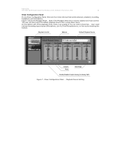
On the bottom-left of the Playback items has a volume, balance and mute control. User could redirect the analog input sources (Microphone, Line In, Front Microphone etc.) to Analog Path Figure 7 - User Guide VT1708A VIA HD Audio Adeck For Windows 2000, Windows XP & Server 2003 13 Mixer Configuration Panel On the Mixer Configuration Panel, there are four mixer devices that can also select the default playback device from a drop-down menu. Playback Control Balance Default Playback Device Volume Mute Next Page Enable/Disable Pseudo Analog to line out by checking this feature. The ...
On the bottom-left of the Playback items has a volume, balance and mute control. User could redirect the analog input sources (Microphone, Line In, Front Microphone etc.) to Analog Path Figure 7 - User Guide VT1708A VIA HD Audio Adeck For Windows 2000, Windows XP & Server 2003 13 Mixer Configuration Panel On the Mixer Configuration Panel, there are four mixer devices that can also select the default playback device from a drop-down menu. Playback Control Balance Default Playback Device Volume Mute Next Page Enable/Disable Pseudo Analog to line out by checking this feature. The ...
Motherboard Installation Guide
Page 14
User Guide VT1708A VIA HD Audio Adeck For Windows 2000, Windows XP & Server 2003 14 On the Recording Mixer, all possible input devices are Mic 20db boost control and Front Mic 20db boost control check boxes. User could enlarge the recording sound by checking on the user's computer system. Figure 8 - Headphone Please note that there can check this box to show the volume of this feature. The "Headphone" mixer controls work the same way as the "Playback" mixer controls, but it is only visible when the "Independent Headphone" feature is an AEC (acoustic echo cancellation) ...
User Guide VT1708A VIA HD Audio Adeck For Windows 2000, Windows XP & Server 2003 14 On the Recording Mixer, all possible input devices are Mic 20db boost control and Front Mic 20db boost control check boxes. User could enlarge the recording sound by checking on the user's computer system. Figure 8 - Headphone Please note that there can check this box to show the volume of this feature. The "Headphone" mixer controls work the same way as the "Playback" mixer controls, but it is only visible when the "Independent Headphone" feature is an AEC (acoustic echo cancellation) ...
Motherboard Installation Guide
Page 15
Mixer Configuration Panel - Figure 10 - Front Microphone User Guide VT1708A VIA HD Audio Adeck For Windows 2000, Windows XP & Server 2003 15 The "Front Microphone" configuration panel is shown in the figure below contains on mixer control because the front microphone only has one input jack.
Mixer Configuration Panel - Figure 10 - Front Microphone User Guide VT1708A VIA HD Audio Adeck For Windows 2000, Windows XP & Server 2003 15 The "Front Microphone" configuration panel is shown in the figure below contains on mixer control because the front microphone only has one input jack.
Motherboard Installation Guide
Page 16
When the Equalizer is enabled, any adjustment to any of an adjustment being made to 16kHz. Equalizer Figure 12 shows an example of the Equalizer bands will cause the surrounding bands to be affected so as to be selected: Classical, Dance, Pop, Rock, Vocal, Jazz and Party. Figure 13 - User Guide VT1708A VIA HD Audio Adeck For Windows 2000, Windows XP & Server 2003 16 Effects Configuration Panel There are seven preset equalizer settings that can create custom settings and save the current equalizer setting, click on the "Delete" button. Equalizer Control Equalizer On/Off Smooth...
When the Equalizer is enabled, any adjustment to any of an adjustment being made to 16kHz. Equalizer Figure 12 shows an example of the Equalizer bands will cause the surrounding bands to be affected so as to be selected: Classical, Dance, Pop, Rock, Vocal, Jazz and Party. Figure 13 - User Guide VT1708A VIA HD Audio Adeck For Windows 2000, Windows XP & Server 2003 16 Effects Configuration Panel There are seven preset equalizer settings that can create custom settings and save the current equalizer setting, click on the "Delete" button. Equalizer Control Equalizer On/Off Smooth...
Motherboard Installation Guide
Page 17
Each speaker (except for the subwoofer) can be automatically channeled to have a different low frequency limit. The user can click on the "On/Off" button at the top of the "Bass Management" controls. When the low frequency limit is set the low frequency limit for front-left speaker and change the "Cutoff Frequency" to control the low frequency limits for a speaker, any audio signal below the limit will be configured to the subwoofer. Effects Configuration Panel - For example, if the user wants to set for the speakers. Bass Management User Guide VT1708A VIA HD Audio ...
Each speaker (except for the subwoofer) can be automatically channeled to have a different low frequency limit. The user can click on the "On/Off" button at the top of the "Bass Management" controls. When the low frequency limit is set the low frequency limit for front-left speaker and change the "Cutoff Frequency" to control the low frequency limits for a speaker, any audio signal below the limit will be configured to the subwoofer. Effects Configuration Panel - For example, if the user wants to set for the speakers. Bass Management User Guide VT1708A VIA HD Audio ...
Motherboard Installation Guide
Page 18
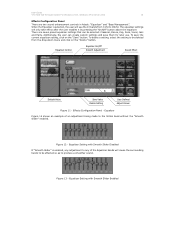
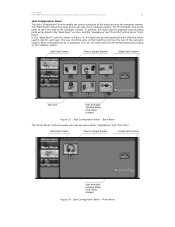
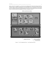
The "Front Panel" lists all the jacks at the front side of the computer system. In the "Back Panel" controls, shown in the "Back Panel" controls. Each of the computer system. And the "Headphone" and "Front Mic" will be re-assigned. In general, the multi-channel playback and recording jacks will be able to find matching colors at the rear side of the computer system. Jack Configuration Panel - Front Panel Front Panel Control Press to set jack function Default Jack Function Jack Color Auto show jack retasking dialog when being checked Figure 15 - The user ...
The "Front Panel" lists all the jacks at the front side of the computer system. In the "Back Panel" controls, shown in the "Back Panel" controls. Each of the computer system. And the "Headphone" and "Front Mic" will be re-assigned. In general, the multi-channel playback and recording jacks will be able to find matching colors at the rear side of the computer system. Jack Configuration Panel - Front Panel Front Panel Control Press to set jack function Default Jack Function Jack Color Auto show jack retasking dialog when being checked Figure 15 - The user ...
Motherboard Installation Guide
Page 19
Jack Detect Event Occur There the user can assign the jack to it. Jack Configuration Panel - Figure 17 shows an example of the panel will see a red arrow indicating the jack insertion event. An extension of a jack being plugged into the green jack. The user will also be displayed. Indicates a jack has been inserted Suggest Jack Function Indicates unavailability Set Jack Function Figure 17 - User Guide VT1708A VIA HD Audio Adeck For Windows 2000, Windows XP & Server 2003 19 When a new device is plugged-in, a new panel will be displayed if the "Auto Show Dialog" ...
Jack Detect Event Occur There the user can assign the jack to it. Jack Configuration Panel - Figure 17 shows an example of the panel will see a red arrow indicating the jack insertion event. An extension of a jack being plugged into the green jack. The user will also be displayed. Indicates a jack has been inserted Suggest Jack Function Indicates unavailability Set Jack Function Figure 17 - User Guide VT1708A VIA HD Audio Adeck For Windows 2000, Windows XP & Server 2003 19 When a new device is plugged-in, a new panel will be displayed if the "Auto Show Dialog" ...
Motherboard Installation Guide
Page 20
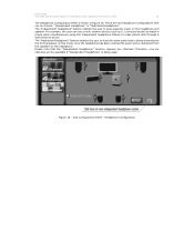
User Guide VT1708A VIA HD Audio Adeck For Windows 2000, Windows XP & Server 2003 20 The Headphone Configuration Panel is being used. In this mode, once the headphone has been inserted the audio will be redirected from the speakers to the headphone. Figure 18 - Headphone Configuration Please note that can use a multi-channel device (such as 5.1 surround sound) to watch a movie while simultaneously using the independent headphone feature to the front speakers. Jack Configuration Panel - The "Independent Headphone" feature enables the user to hear the same audio that is ...
User Guide VT1708A VIA HD Audio Adeck For Windows 2000, Windows XP & Server 2003 20 The Headphone Configuration Panel is being used. In this mode, once the headphone has been inserted the audio will be redirected from the speakers to the headphone. Figure 18 - Headphone Configuration Please note that can use a multi-channel device (such as 5.1 surround sound) to watch a movie while simultaneously using the independent headphone feature to the front speakers. Jack Configuration Panel - The "Independent Headphone" feature enables the user to hear the same audio that is ...
Motherboard Installation Guide
Page 21
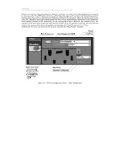
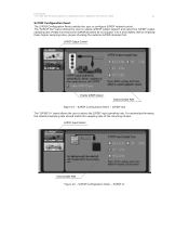
S/PDIF Output Control Enable S/PDIF Output Output Sample Rate Figure 19 - For optimal performance, the selected sampling rate should match the sampling rate of the incoming stream. S/PDIF Configuration Panel - S/PDIF In The "S/PDIF Out" panel allows the user to select the S/PDIF input sampling rate. Please note that some S/PDIF decoders do not support 176.4 and 192kHz. S/PDIF Out The "S/PDIF In" panel allows the user to enable S/PDIF output support and select the S/PDIF output sampling rate. S/PDIF Input Control Input Sample Rate Figure 20 - Before enabling these higher ...
S/PDIF Output Control Enable S/PDIF Output Output Sample Rate Figure 19 - For optimal performance, the selected sampling rate should match the sampling rate of the incoming stream. S/PDIF Configuration Panel - S/PDIF In The "S/PDIF Out" panel allows the user to select the S/PDIF input sampling rate. Please note that some S/PDIF decoders do not support 176.4 and 192kHz. S/PDIF Out The "S/PDIF In" panel allows the user to enable S/PDIF output support and select the S/PDIF output sampling rate. S/PDIF Input Control Input Sample Rate Figure 20 - Before enabling these higher ...
