
F2A55-M LK2 User's Manual
Page 1
Motherboard F2A55-M LK2 Series • F2A55-M LK2 • F2A55-M LK2 PLUS
Motherboard F2A55-M LK2 Series • F2A55-M LK2 • F2A55-M LK2 PLUS

F2A55-M LK2 User's Manual
Page 8
... when trying to select. NOTE: Tips and additional information to help you must press two or more keys simultaneously, the key names are linked with a plus sign (+). If you must press the Enter or Return key. viii Conventions used throughout this guide To ensure that you MUST follow to complete a task...
... when trying to select. NOTE: Tips and additional information to help you must press two or more keys simultaneously, the key names are linked with a plus sign (+). If you must press the Enter or Return key. viii Conventions used throughout this guide To ensure that you MUST follow to complete a task...
F2A55-M LK2 User's Manual
Page 10
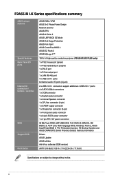
... Internal I/O connectors / buttons / switches BIOS Support DVD Form factor ASUS DIGI+ VRM ASUS 3+2 Phase Power Design Network iControl ASUS EPU ASUS AI Suite II ASUS UEFI BIOS EZ Mode ASUS Anti-Surge Protection ASUS Fan Xpert ASUS CrashFree BIOS 3 ASUS EZ Flash 2 ASUS MyLogo 2™ 100% All high quality conductive polymer (F2A55-M LK2 PLUS only) 1 x PS/2 mouse port (green) 1 x PS/2 keyboard port (purple...
... Internal I/O connectors / buttons / switches BIOS Support DVD Form factor ASUS DIGI+ VRM ASUS 3+2 Phase Power Design Network iControl ASUS EPU ASUS AI Suite II ASUS UEFI BIOS EZ Mode ASUS Anti-Surge Protection ASUS Fan Xpert ASUS CrashFree BIOS 3 ASUS EZ Flash 2 ASUS MyLogo 2™ 100% All high quality conductive polymer (F2A55-M LK2 PLUS only) 1 x PS/2 mouse port (green) 1 x PS/2 keyboard port (purple...
F2A55-M LK2 User's Manual
Page 11
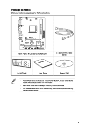
... LAN1_USB12 AUDIO CHA_FAN F2A55-M LK2 PLUS RTL 8111F PCIEX16 PCIEX1_1 Lithium Cell CMOS Power ALC887 Super I/O PCI1 SB_PWR SPDIF_OUTCOM1USBPW5-8 USB78 AAFP AMD® A55 SATA3G_1 SATA3G_2 SPEAKER CLRTC USB56 32Mb BIOS SATA3G_3 SATA3G_4 F_PANEL ASUS F2A55-M LK2 Series motherboard User Guide 2 x Serial ATA 3.0 Gb/s cables 1 x I/O Shield User Guide Support DVD • F2A55-M LK2 Series motherboards include F2A55-M LK2 PLUS and F2A55-M LK2 models.
... LAN1_USB12 AUDIO CHA_FAN F2A55-M LK2 PLUS RTL 8111F PCIEX16 PCIEX1_1 Lithium Cell CMOS Power ALC887 Super I/O PCI1 SB_PWR SPDIF_OUTCOM1USBPW5-8 USB78 AAFP AMD® A55 SATA3G_1 SATA3G_2 SPEAKER CLRTC USB56 32Mb BIOS SATA3G_3 SATA3G_4 F_PANEL ASUS F2A55-M LK2 Series motherboard User Guide 2 x Serial ATA 3.0 Gb/s cables 1 x I/O Shield User Guide Support DVD • F2A55-M LK2 Series motherboards include F2A55-M LK2 PLUS and F2A55-M LK2 models.
F2A55-M LK2 User's Manual
Page 13
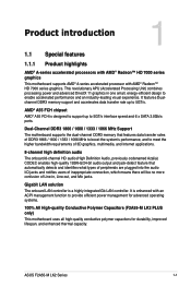
ASUS F2A55-M LK2 Series 1-1 Gigabit LAN solution The onboard LAN controller is designed to support up to 5GT/s. It is enhanced with AMD® Radeon™ HD 7000 ...® A-series accelerated processor with an ACPI management function to provide efficient power management for advanced operating systems. 100% All High-quality Conductive Polymer Capacitors (F2A55-M LK2 PLUS only) This motherboard uses all high-quality conductive polymer capacitors for durability, improved lifespan, and enhanced thermal capacity. It features Dualchannel DDR3 memory support and...
ASUS F2A55-M LK2 Series 1-1 Gigabit LAN solution The onboard LAN controller is designed to support up to 5GT/s. It is enhanced with AMD® Radeon™ HD 7000 ...® A-series accelerated processor with an ACPI management function to provide efficient power management for advanced operating systems. 100% All High-quality Conductive Polymer Capacitors (F2A55-M LK2 PLUS only) This motherboard uses all high-quality conductive polymer capacitors for durability, improved lifespan, and enhanced thermal capacity. It features Dualchannel DDR3 memory support and...
F2A55-M LK2 User's Manual
Page 16
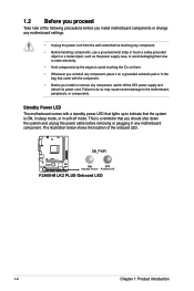
... and unplug the power cable before removing or plugging in soft-off the ATX power supply and detach its power cord. SB_PWR F2A55-M LK2 PLUS ON OFF Standby Power Powered Off F2A55-M LK2 PLUS Onboard LED 1-4 Chapter 1: Product introduction The illustration below shows the location of the following precautions before you install motherboard components or change...
... and unplug the power cable before removing or plugging in soft-off the ATX power supply and detach its power cord. SB_PWR F2A55-M LK2 PLUS ON OFF Standby Power Powered Off F2A55-M LK2 PLUS Onboard LED 1-4 Chapter 1: Product introduction The illustration below shows the location of the following precautions before you install motherboard components or change...
F2A55-M LK2 User's Manual
Page 17
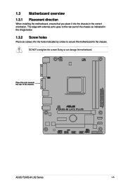
Place this side towards the rear of the chassis as indicated in the image below. 1.3.2 Screw holes Place six screws into the chassis in the correct orientation. The edge with external ports goes to the rear part of the chassis. DO NOT overtighten the screws! Doing so can damage the motherboard. F2A55-M LK2 PLUS ASUS F2A55-M LK2 Series 1-5 1.3 Motherboard overview 1.3.1 Placement direction When installing the motherboard, ensure that you place it into the holes indicated by circles to secure the motherboard to the chassis.
Place this side towards the rear of the chassis as indicated in the image below. 1.3.2 Screw holes Place six screws into the chassis in the correct orientation. The edge with external ports goes to the rear part of the chassis. DO NOT overtighten the screws! Doing so can damage the motherboard. F2A55-M LK2 PLUS ASUS F2A55-M LK2 Series 1-5 1.3 Motherboard overview 1.3.1 Placement direction When installing the motherboard, ensure that you place it into the holes indicated by circles to secure the motherboard to the chassis.
F2A55-M LK2 User's Manual
Page 18
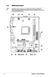
The package contents vary from models. 1.3.3 Motherboard layout F2A55-M LK2 Series motherboards include F2A55-M LK2 PLUS and F2A55-M LK2 models. The layout illustrations in this user guide are for F2A55-M LK2 PLUS only. 1 KBMS 2 3 4 5 17.3cm(6.8in) ATX12V DIGI +VRM CPU_FAN DDR3 DIMM_A1 (64bit, 240...64bit, 240-pin module) VGA DVI 16 KBPWR USBPW1-4 SOCKET FM2 22.6cm(8.9in) 1 USB34 EATXPWR LAN1_USB12 AUDIO CHA_FAN F2A55-M LK2 PLUS RTL 8111F PCIEX16 PCIEX1_1 Lithium Cell CMOS Power SATA3G_1 AMD® A55 SATA3G_2 6 ALC887 Super I/O PCI1 32Mb BIOS SB_PWR ...
The package contents vary from models. 1.3.3 Motherboard layout F2A55-M LK2 Series motherboards include F2A55-M LK2 PLUS and F2A55-M LK2 models. The layout illustrations in this user guide are for F2A55-M LK2 PLUS only. 1 KBMS 2 3 4 5 17.3cm(6.8in) ATX12V DIGI +VRM CPU_FAN DDR3 DIMM_A1 (64bit, 240...64bit, 240-pin module) VGA DVI 16 KBPWR USBPW1-4 SOCKET FM2 22.6cm(8.9in) 1 USB34 EATXPWR LAN1_USB12 AUDIO CHA_FAN F2A55-M LK2 PLUS RTL 8111F PCIEX16 PCIEX1_1 Lithium Cell CMOS Power SATA3G_1 AMD® A55 SATA3G_2 6 ALC887 Super I/O PCI1 32Mb BIOS SB_PWR ...
F2A55-M LK2 User's Manual
Page 19
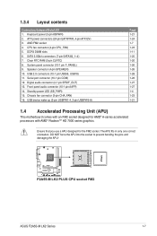
... 1-26 1-28 1-28 1-27 1-27 1-4 1-23 1-21 1.4 Accelerated Processing Unit (APU) This motherboard comes with AMD® Radeon™ HD 7000 series graphics. F2A55-M LK2 PLUS F2A55-M LK2 PLUS CPU socket FM2 ASUS F2A55-M LK2 Series 1-7 Digital audio connector (4-1 pin SPDIF_OUT) 13. Chassis fan connector (3-pin CHA_FAN) 16. Ensure that you use a APU designed for AMD® A-series accelerated...
... 1-26 1-28 1-28 1-27 1-27 1-4 1-23 1-21 1.4 Accelerated Processing Unit (APU) This motherboard comes with AMD® Radeon™ HD 7000 series graphics. F2A55-M LK2 PLUS F2A55-M LK2 PLUS CPU socket FM2 ASUS F2A55-M LK2 Series 1-7 Digital audio connector (4-1 pin SPDIF_OUT) 13. Chassis fan connector (3-pin CHA_FAN) 16. Ensure that you use a APU designed for AMD® A-series accelerated...
F2A55-M LK2 User's Manual
Page 23
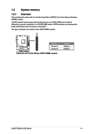
The figure illustrates the location of the DDR3 DIMM sockets: DIMM_A1 DIMM_B1 F2A55-M LK2 PLUS Channel Channel A Channel B F2A55-M LK2 PLUS 240-pin DDR3 DIMM sockets Sockets DIMM_A1 DIMM_B1 ASUS F2A55-M LK2 Series 1-11 A DDR3 module has the same physical dimensions as a DDR2 DIMM but is notched differently to prevent installation on a DDR2 DIMM socket. DDR3 modules are developed for better performance with two Double Data Rate 3 (DDR3) Dual Inline Memory Modules (DIMM) sockets. 1.5 System memory 1.5.1 Overview This motherboard comes with less power consumption.
The figure illustrates the location of the DDR3 DIMM sockets: DIMM_A1 DIMM_B1 F2A55-M LK2 PLUS Channel Channel A Channel B F2A55-M LK2 PLUS 240-pin DDR3 DIMM sockets Sockets DIMM_A1 DIMM_B1 ASUS F2A55-M LK2 Series 1-11 A DDR3 module has the same physical dimensions as a DDR2 DIMM but is notched differently to prevent installation on a DDR2 DIMM socket. DDR3 modules are developed for better performance with two Double Data Rate 3 (DDR3) Dual Inline Memory Modules (DIMM) sockets. 1.5 System memory 1.5.1 Overview This motherboard comes with less power consumption.
F2A55-M LK2 User's Manual
Page 31
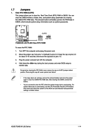
... (C.P.R) feature. F2A55-M LK2 PLUS CLRTC 12 23 Normal (Default) Clear RTC F2A55-M LK2 PLUS Clear RTC RAM To erase the RTC RAM: 1. For system failure due to pins 2-3. Clear RTC RAM (CLRTC) This jumper allows you to pins 1-2. 3. Keep the cap on CLRTC jumper default position. Plug the power cord and turn ON the computer. 4. ASUS F2A55-M LK2 Series...
... (C.P.R) feature. F2A55-M LK2 PLUS CLRTC 12 23 Normal (Default) Clear RTC F2A55-M LK2 PLUS Clear RTC RAM To erase the RTC RAM: 1. For system failure due to pins 2-3. Clear RTC RAM (CLRTC) This jumper allows you to pins 1-2. 3. Keep the cap on CLRTC jumper default position. Plug the power cord and turn ON the computer. 4. ASUS F2A55-M LK2 Series...

F2A55-M LK2 User's Manual
Page 32
... S1 sleep mode (CPU stopped, DRAM refreshed, system running in reduced power mode). F2A55-M LK2 PLUS KBPWR 12 +5V (Default) 23 +5VSB F2A55-M LK2 PLUS Keyboard power setting 1-20 Chapter 1: Product introduction USBPW1-4 12 23 +5V +5VSB (Default) F2A55-M LK2 PLUS USBPW5-8 12 23 +5V +5VSB (Default) F2A55-M LK2 PLUS USB Device Wake Up • The USB device wake-up . • The...
... S1 sleep mode (CPU stopped, DRAM refreshed, system running in reduced power mode). F2A55-M LK2 PLUS KBPWR 12 +5V (Default) 23 +5VSB F2A55-M LK2 PLUS Keyboard power setting 1-20 Chapter 1: Product introduction USBPW1-4 12 23 +5V +5VSB (Default) F2A55-M LK2 PLUS USBPW5-8 12 23 +5V +5VSB (Default) F2A55-M LK2 PLUS USB Device Wake Up • The USB device wake-up . • The...
F2A55-M LK2 User's Manual
Page 34
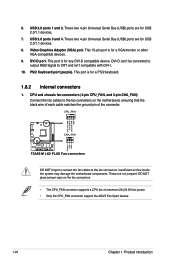
...to the fan connectors. These are for USB 2.0/1.1 devices. 7. CPU_FAN CPU FAN PWM CPU FAN IN CPU FAN PWR GND F2A55-M LK2 PLUS CHA_FAN Rotation +12V GND F2A55-M LK2 PLUS Fan connectors DO NOT forget to connect the fan cables to the fan connectors on the fan connectors. • The CPU_FAN ...that the black wire of each cable matches the ground pin of maximum 2A (24 W) fan power. • Only the CPU_FAN connector support the ASUS Fan Xpert feature. 1-22 Chapter 1: Product introduction These two 4-pin Universal Serial Bus (USB) ports are not jumpers! These two 4-pin Universal ...
...to the fan connectors. These are for USB 2.0/1.1 devices. 7. CPU_FAN CPU FAN PWM CPU FAN IN CPU FAN PWR GND F2A55-M LK2 PLUS CHA_FAN Rotation +12V GND F2A55-M LK2 PLUS Fan connectors DO NOT forget to connect the fan cables to the fan connectors on the fan connectors. • The CPU_FAN ...that the black wire of each cable matches the ground pin of maximum 2A (24 W) fan power. • Only the CPU_FAN connector support the ASUS Fan Xpert feature. 1-22 Chapter 1: Product introduction These two 4-pin Universal Serial Bus (USB) ports are not jumpers! These two 4-pin Universal ...
F2A55-M LK2 User's Manual
Page 35
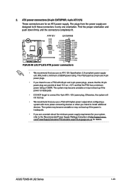
...-us for an ATX power supply. Find the proper orientation and push down firmly until the connectors completely fit. ATX12V EATXPWR +12V DC +12V DC F2A55-M LK2 PLUS GND GND +3 Volts +12 Volts +12 Volts +5V Standby Power OK GND PIN 1 +5 Volts GND +5 Volts GND +3 Volts +3 Volts PIN 1 GND +5 Volts +5...pin power plug can provide at http://support.asus. The plugs from the power supply are for details. This PSU type has 24-pin and 4-pin power plugs. • If you intend to fit these connectors in only one orientation. 2. ASUS F2A55-M LK2 Series 1-23 ATX power connectors (24-pin...
...-us for an ATX power supply. Find the proper orientation and push down firmly until the connectors completely fit. ATX12V EATXPWR +12V DC +12V DC F2A55-M LK2 PLUS GND GND +3 Volts +12 Volts +12 Volts +5V Standby Power OK GND PIN 1 +5 Volts GND +5 Volts GND +3 Volts +3 Volts PIN 1 GND +5 Volts +5...pin power plug can provide at http://support.asus. The plugs from the power supply are for details. This PSU type has 24-pin and 4-pin power plugs. • If you intend to fit these connectors in only one orientation. 2. ASUS F2A55-M LK2 Series 1-23 ATX power connectors (24-pin...
F2A55-M LK2 User's Manual
Page 36
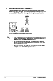
... RSATA_TXN1 RSATA_TXP1 GND GND RSATA_TXP2 RSATA_TXN2 GND RSATA_RXN2 RSATA_RXP2 GND GND RSATA_TXP3 RSATA_TXN3 GND RSATA_RXN3 RSATA_RXP3 GND GND RSATA_TXP4 RSATA_TXN4 GND RSATA_RXN4 RSATA_RXP4 GND F2A55-M LK2 PLUS SATA3G_3 SATA3G_4 F2A55-M LK2 PLUS SATA 3.0Gb/s connectors • These connectors are using Windows® XP SP3 or later version. • When using Serial ATA hard disk drives. See...
... RSATA_TXN1 RSATA_TXP1 GND GND RSATA_TXP2 RSATA_TXN2 GND RSATA_RXN2 RSATA_RXP2 GND GND RSATA_TXP3 RSATA_TXN3 GND RSATA_RXN3 RSATA_RXP3 GND GND RSATA_TXP4 RSATA_TXN4 GND RSATA_RXN4 RSATA_RXP4 GND F2A55-M LK2 PLUS SATA3G_3 SATA3G_4 F2A55-M LK2 PLUS SATA 3.0Gb/s connectors • These connectors are using Windows® XP SP3 or later version. • When using Serial ATA hard disk drives. See...
F2A55-M LK2 User's Manual
Page 37
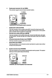
...Connect the chassis power LED cable to hear system beeps and warnings. Ground Reset 4. F_PANEL PWR LED PWR BTN PIN 1 F2A55-M LK2 PLUS HD_LED RESET F2A55-M LK2 PLUS System panel connector • System power LED (2-pin PLED) This 2-pin connector is for the system power LED. The ...from or written to this connector. The IDE LED lights up when you to this connector. SPEAKER F2A55-M LK2 PLUS PIN 1 F2A55-M LK2 PLUS Speaker Out Connector +5V GND GND Speaker Out ASUS F2A55-M LK2 Series 1-25 PLED+ PLEDPWR GND HD_LED+ HD_LED- The system power LED lights up or flashes when...
...Connect the chassis power LED cable to hear system beeps and warnings. Ground Reset 4. F_PANEL PWR LED PWR BTN PIN 1 F2A55-M LK2 PLUS HD_LED RESET F2A55-M LK2 PLUS System panel connector • System power LED (2-pin PLED) This 2-pin connector is for the system power LED. The ...from or written to this connector. The IDE LED lights up when you to this connector. SPEAKER F2A55-M LK2 PLUS PIN 1 F2A55-M LK2 PLUS Speaker Out Connector +5V GND GND Speaker Out ASUS F2A55-M LK2 Series 1-25 PLED+ PLEDPWR GND HD_LED+ HD_LED- The system power LED lights up or flashes when...
F2A55-M LK2 User's Manual
Page 38
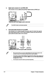
... • The front panel audio I/O module is for an additional Sony/Philips Digital Interface (S/PDIF) port. +5V SPDIFOUT GND F2A55-M LK2 PLUS SPDIF_OUT F2A55-M LK2 PLUS Digital audio connector The S/PDIF module is purchased separately. 7. 6. Connect one end of the front panel audio I /O module that ...1 MIC2 MICPWR Line out_R NC Line out_L PORT1 L PORT1 R PORT2 R SENSE_SEND PORT2 L F2A55-M LK2 PLUS HD-audio-compliant Legacy AC'97 pin definition compliant definition F2A55-M LK2 PLUS Front panel audio connector • We recommend that supports either High Definition Audio or AC`97...
... • The front panel audio I/O module is for an additional Sony/Philips Digital Interface (S/PDIF) port. +5V SPDIFOUT GND F2A55-M LK2 PLUS SPDIF_OUT F2A55-M LK2 PLUS Digital audio connector The S/PDIF module is purchased separately. 7. 6. Connect one end of the front panel audio I /O module that ...1 MIC2 MICPWR Line out_R NC Line out_L PORT1 L PORT1 R PORT2 R SENSE_SEND PORT2 L F2A55-M LK2 PLUS HD-audio-compliant Legacy AC'97 pin definition compliant definition F2A55-M LK2 PLUS Front panel audio connector • We recommend that supports either High Definition Audio or AC`97...
F2A55-M LK2 User's Manual
Page 39
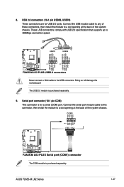
COM1 CTS DSR DTR RXD RI PIN 1 RTS GND TXD DCD F2A55-M LK2 PLUS F2A55-M LK2 PLUS Serial port (COM1) connector The COM module is purchased separately. 9. Connect the USB module cable to any of these connectors, then ...5V USB_P8USB_P8+ GND NC F2A55-M LK2 PLUS PIN 1 PIN 1 USB+5V USB_P5USB_P5+ GND USB+5V USB_P7USB_P7+ GND F2A55-M LK2 PLUS USB2.0 connectors Never connect a 1394 cable to 480Mbps connection speed. Doing so will damage the motherboard! USB 2.0 connectors (10-1 pin USB56, USB78) These connectors are for a serial (COM) port. ASUS F2A55-M LK2 Series 1-27 The USB...
COM1 CTS DSR DTR RXD RI PIN 1 RTS GND TXD DCD F2A55-M LK2 PLUS F2A55-M LK2 PLUS Serial port (COM1) connector The COM module is purchased separately. 9. Connect the USB module cable to any of these connectors, then ...5V USB_P8USB_P8+ GND NC F2A55-M LK2 PLUS PIN 1 PIN 1 USB+5V USB_P5USB_P5+ GND USB+5V USB_P7USB_P7+ GND F2A55-M LK2 PLUS USB2.0 connectors Never connect a 1394 cable to 480Mbps connection speed. Doing so will damage the motherboard! USB 2.0 connectors (10-1 pin USB56, USB78) These connectors are for a serial (COM) port. ASUS F2A55-M LK2 Series 1-27 The USB...
F2A55-M LK2 User's Manual
Page 43
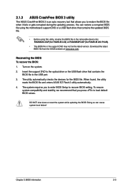
...system compatibility and stability, we recommend that you to enter BIOS Setup to load default BIOS values. The utility automatically checks the devices for F2A55-M LK2 PLUS). • The BIOS file in the support DVD may not be the latest version. Recovering the BIOS To recover the BIOS: 1. ...the system while updating the BIOS! The system requires you press to recover BIOS setting. You can cause system boot failure! 2.1.3 ASUS CrashFree BIOS 3 utility The ASUS CrashFree BIOS 3 is an auto recovery tool that allows you to the USB port. 3. Doing so can restore a corrupted ...
...system compatibility and stability, we recommend that you to enter BIOS Setup to load default BIOS values. The utility automatically checks the devices for F2A55-M LK2 PLUS). • The BIOS file in the support DVD may not be the latest version. Recovering the BIOS To recover the BIOS: 1. ...the system while updating the BIOS! The system requires you press to recover BIOS setting. You can cause system boot failure! 2.1.3 ASUS CrashFree BIOS 3 utility The ASUS CrashFree BIOS 3 is an auto recovery tool that allows you to the USB port. 3. Doing so can restore a corrupted ...
F2A55-M LK2 User's Manual
Page 45
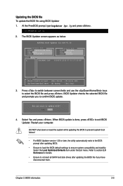
.... When BIOS update is done, press to select the BIOS file and press . Refer to section 2.9 Exit menu for DOS V1.30 Current ROM BOARD: F2A55-M LK2 PLUS VER: 0201 DATE: 07/13/2012 Update ROM BOARD: Unknown VER: Unknown DATE: Unknown PATH: A:\ A: F2A5MKP2.CAP 8390656 2012-07-13 17:30:48 Note...
.... When BIOS update is done, press to select the BIOS file and press . Refer to section 2.9 Exit menu for DOS V1.30 Current ROM BOARD: F2A55-M LK2 PLUS VER: 0201 DATE: 07/13/2012 Update ROM BOARD: Unknown VER: Unknown DATE: Unknown PATH: A:\ A: F2A5MKP2.CAP 8390656 2012-07-13 17:30:48 Note...


