
Service Manual
Page 13
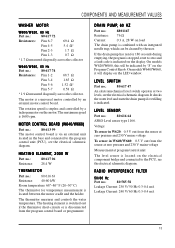
...AND MEASUREMENT VALUES WASHER MOTOR W600/W620, 60 Hz Part no.: 80 617 72 Resistances: Pins 6-7 69.4 Ω Pins 4-5 5.4 Ω* Pins 2-3 1.7 Ω Pins 1-3 0.7 Ω * 1.7 Ω measured diagonally across the collector W640/W660, 60 Hz Part no .: 80 616 64 ASKO Level sensor type 1166. ... schematic diagram. The maximum speed is disconnected from the sensor at zero pressure and 230 V mains voltage Measurement at two levels, see the electrical schematic diagram. The heating element is switched out if the thermistor short-circuits or is 1600 rpm. It checks the...
...AND MEASUREMENT VALUES WASHER MOTOR W600/W620, 60 Hz Part no.: 80 617 72 Resistances: Pins 6-7 69.4 Ω Pins 4-5 5.4 Ω* Pins 2-3 1.7 Ω Pins 1-3 0.7 Ω * 1.7 Ω measured diagonally across the collector W640/W660, 60 Hz Part no .: 80 616 64 ASKO Level sensor type 1166. ... schematic diagram. The maximum speed is disconnected from the sensor at zero pressure and 230 V mains voltage Measurement at two levels, see the electrical schematic diagram. The heating element is switched out if the thermistor short-circuits or is 1600 rpm. It checks the...

Service Manual
Page 52
... 8061924 52 Remove the protection device by inserting it 1/4 turn and take it to the level switch and level sensor. 4. W620 and W660: Remove the lower cover (see page 29). 2. Twist the pressure chamber 1/4 turn . 6. Align the device and press it into the bracket and twisting it ...5. Join the rubber hose and the corrugated hose together with a hose clip. W600 and W640: Remove the front panel (see page 26). W600 and W640: Replace the front panel. OVERFLOW PROTECTION DEVICE (W660) AND PRESSURE CHAMBER CHANGING THE OVERFLOW PROTECTION DEVICE (W660) 1. From the rear: Remove the...
... 8061924 52 Remove the protection device by inserting it 1/4 turn and take it to the level switch and level sensor. 4. W620 and W660: Remove the lower cover (see page 29). 2. Twist the pressure chamber 1/4 turn . 6. Align the device and press it into the bracket and twisting it ...5. Join the rubber hose and the corrugated hose together with a hose clip. W600 and W640: Remove the front panel (see page 26). W600 and W640: Replace the front panel. OVERFLOW PROTECTION DEVICE (W660) AND PRESSURE CHAMBER CHANGING THE OVERFLOW PROTECTION DEVICE (W660) 1. From the rear: Remove the...

Service Manual
Page 65
...39 Input terminal block 47 Installation 3, 4, 5, 6 Interrupting a program (W600/W620) ....... 57 K Knobs (W600/W620 24 L Language, changing on LED window ......... 62 Laundry Problems 12 LED window (W640/W660 59 Level sensor 13, 46 Level switch 13, 45 Lower cover (W620/W660 29 M Main power button 23... 60 restoring 59 Pressure chamber 52 Processor Control Unit (PCU) (W640/W660 47 Programmer (W600/W620 46 Programs changes (W640/W660 59 customizing (W640/W660 59 W600 55 W620 56 W640 and W660 60 Pump housing 40 Pushbuttons pad (W640/W660 25 switches 23 W600 and W620 24 ...
...39 Input terminal block 47 Installation 3, 4, 5, 6 Interrupting a program (W600/W620) ....... 57 K Knobs (W600/W620 24 L Language, changing on LED window ......... 62 Laundry Problems 12 LED window (W640/W660 59 Level sensor 13, 46 Level switch 13, 45 Lower cover (W620/W660 29 M Main power button 23... 60 restoring 59 Pressure chamber 52 Processor Control Unit (PCU) (W640/W660 47 Programmer (W600/W620 46 Programs changes (W640/W660 59 customizing (W640/W660 59 W600 55 W620 56 W640 and W660 60 Pump housing 40 Pushbuttons pad (W640/W660 25 switches 23 W600 and W620 24 ...

