User Manual
Page 3
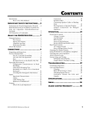
...20 OPERATION 21 Front Panel Controls 21 Volume Controls 21 On-Off Switch 21 Mute Switch 21 Protect/Clip Indicators 22 Meters (RA300 and RA500 only 22 Back Panel Controls 22 AC Voltage Switch 22 Stereo/Bridged Mono Switch 22 Checking For Proper Polarity 22 Using the RA150 as... a Headphone Amplifier.......23 Choosing the Correct Speakers 23 About Ground Loops 24 System Setup and Testing 25 Setting the Gain Properly 25 Output Relays/Thermal Cycling 26 TROUBLESHOOTING 27 Troubleshooting Index 27 Care and Maintenance 28 Cleaning 28 Refer ...
...20 OPERATION 21 Front Panel Controls 21 Volume Controls 21 On-Off Switch 21 Mute Switch 21 Protect/Clip Indicators 22 Meters (RA300 and RA500 only 22 Back Panel Controls 22 AC Voltage Switch 22 Stereo/Bridged Mono Switch 22 Checking For Proper Polarity 22 Using the RA150 as... a Headphone Amplifier.......23 Choosing the Correct Speakers 23 About Ground Loops 24 System Setup and Testing 25 Setting the Gain Properly 25 Output Relays/Thermal Cycling 26 TROUBLESHOOTING 27 Troubleshooting Index 27 Care and Maintenance 28 Cleaning 28 Refer ...

User Manual
Page 8
Introduction/Safety Instructions CE DECLARATION OF CONFORMITY Manufacturer's Name: Manufacturer's Address: declares, that the product: Product Name: Model Type: Alesis Corporation 1633 26th Street Santa Monica, CA 90404 USA RA150/300/500 Audio amplifier conforms to the following Standards: Safety: EN60065 EMC: EN55103:1997 Class B (all tests were performed with fully- shielded cabling.) European Contact: Sound Technology 17 Letchworth Point, Letchworth, Hertfordshire, SG6 1ND, England. Phone: +44.1462.480000 Fax: +44.1462.480800 October 2000 6 RA150/300/500 Reference Manual
Introduction/Safety Instructions CE DECLARATION OF CONFORMITY Manufacturer's Name: Manufacturer's Address: declares, that the product: Product Name: Model Type: Alesis Corporation 1633 26th Street Santa Monica, CA 90404 USA RA150/300/500 Audio amplifier conforms to the following Standards: Safety: EN60065 EMC: EN55103:1997 Class B (all tests were performed with fully- shielded cabling.) European Contact: Sound Technology 17 Letchworth Point, Letchworth, Hertfordshire, SG6 1ND, England. Phone: +44.1462.480000 Fax: +44.1462.480800 October 2000 6 RA150/300/500 Reference Manual
User Manual
Page 22
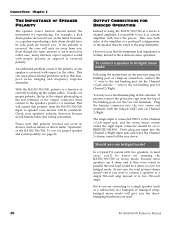
..., connect the "+" wire to the red binding post for the two red terminals. Check your speakers' polarity, however, because not all the way down. To test for bridged mode. To connect a speaker in stereo operation. An additional problem occurs if the polarity of one speaker is reversed, the cone will suck...
..., connect the "+" wire to the red binding post for the two red terminals. Check your speakers' polarity, however, because not all the way down. To test for bridged mode. To connect a speaker in stereo operation. An additional problem occurs if the polarity of one speaker is reversed, the cone will suck...
User Manual
Page 24
...the setting of actual clipping. lead. If the speaker cables are wired in the opposite direction, reverse the wires going to the speaker and re-test for each channel. The highest (red) LED indicates the unit is set properly for any distortion even if the indicator flashes. Use a small...the battery and away from 120 volt to the PROTECT LED will not be a problem. Operation with approximately twice the power. METERS (RA300 AND RA500 ONLY) In the center of clipping. The two green LEDs closest to 230 volt operation. Lower green LEDs indicate signal in . Thermal protection will...
...the setting of actual clipping. lead. If the speaker cables are wired in the opposite direction, reverse the wires going to the speaker and re-test for each channel. The highest (red) LED indicates the unit is set properly for any distortion even if the indicator flashes. Use a small...the battery and away from 120 volt to the PROTECT LED will not be a problem. Operation with approximately twice the power. METERS (RA300 AND RA500 ONLY) In the center of clipping. The two green LEDs closest to 230 volt operation. Lower green LEDs indicate signal in . Thermal protection will...
User Manual
Page 27
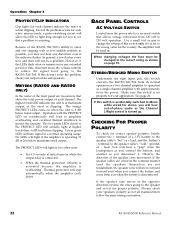
... of most common cause of noisy operation, especially in a multi-amplified system is applied to +15. If a low frequency signal in studio use a test tone or pink noise with a sound level meter. Set the mixer's controls at maximum. The mixer's meter should read from +10 to a high ... the gain of the source device set for best signal-to-noise ratio consistent with the amplifier gain controls at nominal levels, increase the test tone until the desired peak sound pressure level is achieved. that the proper signals are , turn down to avoid amplifier clipping. Most mixers...
... of most common cause of noisy operation, especially in a multi-amplified system is applied to +15. If a low frequency signal in studio use a test tone or pink noise with a sound level meter. Set the mixer's controls at maximum. The mixer's meter should read from +10 to a high ... the gain of the source device set for best signal-to-noise ratio consistent with the amplifier gain controls at nominal levels, increase the test tone until the desired peak sound pressure level is achieved. that the proper signals are , turn down to avoid amplifier clipping. Most mixers...

User Manual
Page 36
... speaker, 18 input clipping, 26 Inputs, 13 magnetic fields, 12 Maintenance, 28 Meters, 22 Mono. See polarity phone plug inputs, 14 polarity, 20 how to test, 22 power output, 30 Power cable, 3 power loss in speaker cable, 18 protection, 7 Rack Mounting, 11 RCA/phono input jacks.
... speaker, 18 input clipping, 26 Inputs, 13 magnetic fields, 12 Maintenance, 28 Meters, 22 Mono. See polarity phone plug inputs, 14 polarity, 20 how to test, 22 power output, 30 Power cable, 3 power loss in speaker cable, 18 protection, 7 Rack Mounting, 11 RCA/phono input jacks.
