

User Guide
Page 1
...equipment does cause by turning the equipment off and on a circuit different from the wall electrical outlet if you are designed to part 15 of time. Reorient or relocate the receiving antenna. - Connect the equipment into an outlet on , the user is connected. - Unplugging the... TV will not occur in a residential installation. Please use a power cable is no main power switch for this equipment. FCC Warning To assure ...
...equipment does cause by turning the equipment off and on a circuit different from the wall electrical outlet if you are designed to part 15 of time. Reorient or relocate the receiving antenna. - Connect the equipment into an outlet on , the user is connected. - Unplugging the... TV will not occur in a residential installation. Please use a power cable is no main power switch for this equipment. FCC Warning To assure ...
User Guide
Page 4
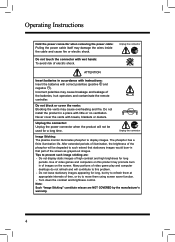
...video games and computers on the screen. Note: Such "Image Sticking" constitute misuse are : - Unplug the connector Image Sticking: The plasma monitor illuminates phosphor to move them at appropriate intervals of images on this problem. - Do not leave stationary images appearing for long, but...screen as grayed-out images. Unplug the connector: Unplug the power connector when the product will not be degraded to such extend that part of electric shock. The phosphor has a finite illumination life. Incorrect polarities may promote burn in a place with correct polarities ...
...video games and computers on the screen. Note: Such "Image Sticking" constitute misuse are : - Unplug the connector Image Sticking: The plasma monitor illuminates phosphor to move them at appropriate intervals of images on this problem. - Do not leave stationary images appearing for long, but...screen as grayed-out images. Unplug the connector: Unplug the power connector when the product will not be degraded to such extend that part of electric shock. The phosphor has a finite illumination life. Incorrect polarities may promote burn in a place with correct polarities ...

User Guide
Page 5
... discharge unit (NEC Section 810-20) Electric service equipment Grounding conductors (NEC Section 810-21) Ground clamp Power service grounding electrode system (NEC Art 250 Part H) Use extreme care to make sure you are never in contact with, such as a ladder or screwdriver) can accidentally touch overhead power lines. or b). Always...
... discharge unit (NEC Section 810-20) Electric service equipment Grounding conductors (NEC Section 810-21) Ground clamp Power service grounding electrode system (NEC Art 250 Part H) Use extreme care to make sure you are never in contact with, such as a ladder or screwdriver) can accidentally touch overhead power lines. or b). Always...

User Guide
Page 7
... Menu 27 ☼ Adjustment of "Balance", "Bass" or "Treble 27 ☼ Selection of "Acoustic Cinema Enhancement 27 ☼ Selection of "SPDIF Type 27 6.4.3 TV Page Menu 28 ☼ Using the "Tuner Mode" ..... 28 ☼ Using the "Channel Scan".. 28 ☼ Using the "Range Scan" .... 29 ☼... 32 Selection of "Time Zone".... 32 Using of "Time 33 Selection of "Analog Closed . Technical Specification 42 8. Caption 34 Selection of "Digital Closed Caption 35 Selection of "Digital Caption Style 35 ☼ To "Reset Default 36 ☼...
... Menu 27 ☼ Adjustment of "Balance", "Bass" or "Treble 27 ☼ Selection of "Acoustic Cinema Enhancement 27 ☼ Selection of "SPDIF Type 27 6.4.3 TV Page Menu 28 ☼ Using the "Tuner Mode" ..... 28 ☼ Using the "Channel Scan".. 28 ☼ Using the "Range Scan" .... 29 ☼... 32 Selection of "Time Zone".... 32 Using of "Time 33 Selection of "Analog Closed . Technical Specification 42 8. Caption 34 Selection of "Digital Closed Caption 35 Selection of "Digital Caption Style 35 ☼ To "Reset Default 36 ☼...

User Guide
Page 10
... OSD Menu screen. 4. Names and Functions of the buttons are used as follows: STANDBY: Press (STANDBY) to display the source menu. STANDBY The functions of Parts 4.1 Front View Sketch map 1 & 2 3 1 (IR) Infrared Receiver: Receives IR signals from the OSD menu or the input menu, press it to scan through... channels, press and hold down from the front panel. They are : TV, AV, S-Video, YPbPr 1, YPbPr 2, VGA , HDMI 1 or HDMI 2 signal source. SOURCE: Press to turn on and turn on / Standby) LED: Press (Power) ...
... OSD Menu screen. 4. Names and Functions of the buttons are used as follows: STANDBY: Press (STANDBY) to display the source menu. STANDBY The functions of Parts 4.1 Front View Sketch map 1 & 2 3 1 (IR) Infrared Receiver: Receives IR signals from the OSD menu or the input menu, press it to scan through... channels, press and hold down from the front panel. They are : TV, AV, S-Video, YPbPr 1, YPbPr 2, VGA , HDMI 1 or HDMI 2 signal source. SOURCE: Press to turn on and turn on / Standby) LED: Press (Power) ...