Service Manual
Page 5
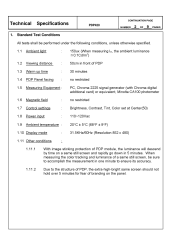
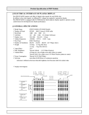
... PDP Panel facing : : : : 150ux (When measuring IB, the ambient luminance ≦0.1Cd/m2) 50cm in front of PDP 30 minutes no restricted PC, Chroma 2225 signal generator (with Chroma digital additional card) or equivalent, Minolta CA100 photometer no restricted Brightness, Contrast, Tint, Color set at Center(50) 110~120Vac 20°...
... PDP Panel facing : : : : 150ux (When measuring IB, the ambient luminance ≦0.1Cd/m2) 50cm in front of PDP 30 minutes no restricted PC, Chroma 2225 signal generator (with Chroma digital additional card) or equivalent, Minolta CA100 photometer no restricted Brightness, Contrast, Tint, Color set at Center(50) 110~120Vac 20°...
Service Manual
Page 6
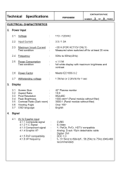
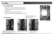
Power Input 2.1 2.2 2.3 2.4 2.5 Voltage Input Current Maximum Inrush Current Test condition Frequency Power Consumption Test condition Power Factor Withstanding voltage 110 ~120VAC 3.5 / 1.5A Technical Specifications CONTINUATION PAGE PDP4206EM NUMBER 3 OF 9 PAGES ELECTRICAL CHARACTERISTICS 2.
Power Input 2.1 2.2 2.3 2.4 2.5 Voltage Input Current Maximum Inrush Current Test condition Frequency Power Consumption Test condition Power Factor Withstanding voltage 110 ~120VAC 3.5 / 1.5A Technical Specifications CONTINUATION PAGE PDP4206EM NUMBER 3 OF 9 PAGES ELECTRICAL CHARACTERISTICS 2.
Service Manual
Page 8
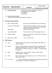
... 8.1 8.2 Audio Picture : : Adjust or Select Volume; Speaker. Scaling (Picture changes According to Fill or One to select the input signals source. Position Phase, Frequency) Position; OSD V. Language. Source Scan; Movie Blocking; CC Mode; UP/Down Button Volume Up/ Down ...or Select Brightness; OSD H. Turn on OSD menu increase or decrease the data-bar. Balance; DNR; Technical Specifications : CONTINUATION PAGE PDP4206EM NUMBER 5 OF 9 PAGES 6.11 Color temperature Contrast at Natural x=0.285±0.02 y=0.293±0.02 6.12 Cell Defect Specifications ...
... 8.1 8.2 Audio Picture : : Adjust or Select Volume; Speaker. Scaling (Picture changes According to Fill or One to select the input signals source. Position Phase, Frequency) Position; OSD V. Language. Source Scan; Movie Blocking; CC Mode; UP/Down Button Volume Up/ Down ...or Select Brightness; OSD H. Turn on OSD menu increase or decrease the data-bar. Balance; DNR; Technical Specifications : CONTINUATION PAGE PDP4206EM NUMBER 5 OF 9 PAGES 6.11 Color temperature Contrast at Natural x=0.285±0.02 y=0.293±0.02 6.12 Cell Defect Specifications ...
Service Manual
Page 10
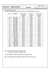
Press "DISPLAY" button to confirm the input signal format. VGA could not support * of signal mode. - Technical Specifications CONTINUATION PAGE PDP4206EM NUMBER 7 OF 9 PAGES 12. Supportthe Signal Mode The PDP can support the different from DVI or VGA Signal Mode in five seconds if you change them. Note: Some data will be updated in 24 kinds....00 78.75 94.50 80.37 108.03 94.51 111.51 126.00 108.04 74.19 Note: DVI could not support # of signal mode.
Press "DISPLAY" button to confirm the input signal format. VGA could not support * of signal mode. - Technical Specifications CONTINUATION PAGE PDP4206EM NUMBER 7 OF 9 PAGES 12. Supportthe Signal Mode The PDP can support the different from DVI or VGA Signal Mode in five seconds if you change them. Note: Some data will be updated in 24 kinds....00 78.75 94.50 80.37 108.03 94.51 111.51 126.00 108.04 74.19 Note: DVI could not support # of signal mode.

Service Manual
Page 13
Common sustain driver Scan Driver Block Diagram Product Specification of PDP Module LVDS Input Control Signal (Serial Interface) APL Data Input Interface Controller Memory Controller Vs(180V~190V) Va(55V~65V) Vcc(+5V) Driver Timing Controller Display data, Driver timing Color Plasma Display Panel 852 X 480 pixels Address Driver Applied Voltage level is specified at the time when Full-White pattern is displayed on the panel.
Common sustain driver Scan Driver Block Diagram Product Specification of PDP Module LVDS Input Control Signal (Serial Interface) APL Data Input Interface Controller Memory Controller Vs(180V~190V) Va(55V~65V) Vcc(+5V) Driver Timing Controller Display data, Driver timing Color Plasma Display Panel 852 X 480 pixels Address Driver Applied Voltage level is specified at the time when Full-White pattern is displayed on the panel.
Service Manual
Page 36
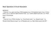
Basic Operations & Circuit Description MODULE There are 5 pc.s PCBs including 1 pc. SET There are 1 pc. Tuner/Audio board, 1 pc. L/R Speakers and 1 pc. Remote Control Receiver board, 1 pc. Main (Video) board in the Module. Keypad board, 1 pc. Power board in the SET. Control (Signal Input) and 1 pc. panel and 8 pc.s PCB including 2 pc.s Y/Z Sustainer board, 2 pc.s Y Drive board, 2 pc.s X (left and right) Extension PCB, 1 pc.
Basic Operations & Circuit Description MODULE There are 5 pc.s PCBs including 1 pc. SET There are 1 pc. Tuner/Audio board, 1 pc. L/R Speakers and 1 pc. Remote Control Receiver board, 1 pc. Main (Video) board in the Module. Keypad board, 1 pc. Power board in the SET. Control (Signal Input) and 1 pc. panel and 8 pc.s PCB including 2 pc.s Y/Z Sustainer board, 2 pc.s Y Drive board, 2 pc.s X (left and right) Extension PCB, 1 pc.
Service Manual
Page 37
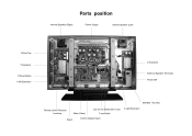
Parts position Internal Speaker (Right) Power Supply Internal Speaker (Left) Y-Drive Top Z-Sustainer Y-Sustainer External Speaker Terminals Y-Drive Bottom X left Extension Power SW EMI filter + AC Inlet only for the Model with Turner Main (Video) Stand Tuner/Audio X right Extension Remote control Receiver Local key Control (Signal Input)
Parts position Internal Speaker (Right) Power Supply Internal Speaker (Left) Y-Drive Top Z-Sustainer Y-Sustainer External Speaker Terminals Y-Drive Bottom X left Extension Power SW EMI filter + AC Inlet only for the Model with Turner Main (Video) Stand Tuner/Audio X right Extension Remote control Receiver Local key Control (Signal Input)
Service Manual
Page 38
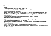
...To provide power for output to the panel. 6. Main (Video InterFace) board: To converter TV signals, S signals, AV signals, Y Pb/ Cb Pr/Cr signals, DVI signals and D-SUB signals to digital ones and to transmit to the internal or external speakers of which selected. Y-Drive ...board: Receive signal from Control and high voltage supply. (2). Control board: Dealing with the digital signal for PCBs. 2. Output scanning waveform for Module. 5. Y-Sustainer / Z-Sustainer board: (1). Receiving the signals from Y sustainer, output horizontal scanning waveform ...
...To provide power for output to the panel. 6. Main (Video InterFace) board: To converter TV signals, S signals, AV signals, Y Pb/ Cb Pr/Cr signals, DVI signals and D-SUB signals to digital ones and to transmit to the internal or external speakers of which selected. Y-Drive ...board: Receive signal from Control and high voltage supply. (2). Control board: Dealing with the digital signal for PCBs. 2. Output scanning waveform for Module. 5. Y-Sustainer / Z-Sustainer board: (1). Receiving the signals from Y sustainer, output horizontal scanning waveform ...
Service Manual
Page 39
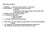
... light. Audio Bard: a. Sustainer: The component working temperature is about 55oC. PCB failure analysis 1. No voice. Noise 7. Y/Z - Abnormal noise on screen. 3. No picture but with signals. 6. No picture. 2. b. Y - Lacking color, Bad color scale. Z - b. POWER: No picture, no power output. 4. d. No voice. (Make sure status: Mute / Internal, External speaker) b. Sustainer: a. If the...
... light. Audio Bard: a. Sustainer: The component working temperature is about 55oC. PCB failure analysis 1. No voice. Noise 7. Y/Z - Abnormal noise on screen. 3. No picture but with signals. 6. No picture. 2. b. Y - Lacking color, Bad color scale. Z - b. POWER: No picture, no power output. 4. d. No voice. (Make sure status: Mute / Internal, External speaker) b. Sustainer: a. If the...

Service Manual
Page 40
..., Vs ON) to search available signal sources. Basic operation of Plasma Display 1. This time VIF will be shut down by Audio AMP and transmitted to Power. When the ON signal from Key Switch or Remote Receiver. 2. If some abnormal signals are detected (for ON signals from Key Switch or Remote Receiver ..., Micro Processor will be amplified by Power off. After turning on the panel and start to PCBs working. If the audio signals input, them will send signals to display back light, OSD on power switch, power board sends 5Vst-by Volt to Micro Processor IC waiting for example: ...
..., Vs ON) to search available signal sources. Basic operation of Plasma Display 1. This time VIF will be shut down by Audio AMP and transmitted to Power. When the ON signal from Key Switch or Remote Receiver. 2. If some abnormal signals are detected (for ON signals from Key Switch or Remote Receiver ..., Micro Processor will be amplified by Power off. After turning on the panel and start to PCBs working. If the audio signals input, them will send signals to display back light, OSD on power switch, power board sends 5Vst-by Volt to Micro Processor IC waiting for example: ...
Service Manual
Page 43
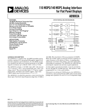
... However, no responsibility is assumed by implication or otherwise under any infringements of patents or other rights of Hsync. When the COAST signal is presented, the PLL maintains its use , nor for any patent or patent rights of 300 MHz supports resolutions up to SXGA..." Midscale Clamping Power-Down Mode Low Power: 500 mW Typical 4:2:2 Output Format Mode APPLICATIONS RGB Graphics Processing LCD Monitors and Projectors Plasma Display Panels Scan Converters Microdisplays Digital TV 110 MSPS/140 MSPS Analog Interface for Flat Panel Displays AD9883A FUNCTIONAL BLOCK DIAGRAM RAIN CLAMP ...
... However, no responsibility is assumed by implication or otherwise under any infringements of patents or other rights of Hsync. When the COAST signal is presented, the PLL maintains its use , nor for any patent or patent rights of 300 MHz supports resolutions up to SXGA..." Midscale Clamping Power-Down Mode Low Power: 500 mW Typical 4:2:2 Output Format Mode APPLICATIONS RGB Graphics Processing LCD Monitors and Projectors Plasma Display Panels Scan Converters Microdisplays Digital TV 110 MSPS/140 MSPS Analog Interface for Flat Panel Displays AD9883A FUNCTIONAL BLOCK DIAGRAM RAIN CLAMP ...
Service Manual
Page 44
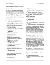
...Black Level Stretch Saturation Control 1.6 Host Interface • Three, on -chip detection logic block that corrects non-standard input signals before processing. It provides high quality video processing including video noise reduction, motion compensation, sharpness enhancement, and resolution enhancement....mode application 1.7 General Description and Applications The NV320 is a CMOS mixed signal circuit highly integrated with three, 10-bit digital-toanalog converters controlled by handling non-standard video input signals. Digital 8-bit YUV (ITU-R 656) - The NV320 accepts 16-...
...Black Level Stretch Saturation Control 1.6 Host Interface • Three, on -chip detection logic block that corrects non-standard input signals before processing. It provides high quality video processing including video noise reduction, motion compensation, sharpness enhancement, and resolution enhancement....mode application 1.7 General Description and Applications The NV320 is a CMOS mixed signal circuit highly integrated with three, 10-bit digital-toanalog converters controlled by handling non-standard video input signals. Digital 8-bit YUV (ITU-R 656) - The NV320 accepts 16-...
Service Manual
Page 47
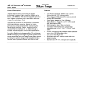
... into standby mode with a digital interface solution that the interface will be stable through a number of the system level issues associated with high-speed mixed signal design, providing the system designer with clock detect circuitry Standard and Pb-free packages (see page 25). SiI 161B PanelLink Receiver Data Sheet General Description...
... into standby mode with a digital interface solution that the interface will be stable through a number of the system level issues associated with high-speed mixed signal design, providing the system designer with clock detect circuitry Standard and Pb-free packages (see page 25). SiI 161B PanelLink Receiver Data Sheet General Description...
Service Manual
Page 49
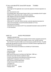
... I2C - Variable Surround Effect Level via I2C (4-levels) - High integration level with only two speakers. I2C-bus transceiver. I2C BUS Interface 8 to process the audio signal for TV, such as tone control, balance, volume, mute, and AGC functions. The AGC circuit reduces volume difference among input sources. - Stereo pilot PLL circuit...
... I2C - Variable Surround Effect Level via I2C (4-levels) - High integration level with only two speakers. I2C-bus transceiver. I2C BUS Interface 8 to process the audio signal for TV, such as tone control, balance, volume, mute, and AGC functions. The AGC circuit reduces volume difference among input sources. - Stereo pilot PLL circuit...
Service Manual
Page 54
...R G B R G B R G B R G B R G B R G B R G B R G B R G B R G B 1.080 479th pixel row 480th pixel row R G B R G B R G B R G B R G B R G B R G B R G B In addition to the video signals, six different DC voltages are required to optimize system control factor for each RGB color. Product Specification of PDP Module ‰ ELECTRICAL INTERFACE OF... PLASMA DISPLAY The PDP42V6#### requires only 8bits of digital video signals for showing the best display performance. ‰ GENERAL SPECFICATIONS 9 Model Name ...
...R G B R G B R G B R G B R G B R G B R G B R G B R G B R G B 1.080 479th pixel row 480th pixel row R G B R G B R G B R G B R G B R G B R G B R G B In addition to the video signals, six different DC voltages are required to optimize system control factor for each RGB color. Product Specification of PDP Module ‰ ELECTRICAL INTERFACE OF... PLASMA DISPLAY The PDP42V6#### requires only 8bits of digital video signals for showing the best display performance. ‰ GENERAL SPECFICATIONS 9 Model Name ...

Service Manual
Page 58
LABEL ‰ LABEL Sticking Position Coner Plate E/X Tube 3211QKE008A P/N (carved) Y-SUS Z - SUS CONTROLLER X left Signal Input (R,G,B,H/Vsync.) X right ‰ Identification Label : LABEL 7.0 2.5 Model Name Bar Code (Code 128, Contains the manufacture No.) Manufacture No. Product Specification of LG Electronics Manufactured date (Year & Month) Manufactured place The trade name of PDP Module 8.
LABEL ‰ LABEL Sticking Position Coner Plate E/X Tube 3211QKE008A P/N (carved) Y-SUS Z - SUS CONTROLLER X left Signal Input (R,G,B,H/Vsync.) X right ‰ Identification Label : LABEL 7.0 2.5 Model Name Bar Code (Code 128, Contains the manufacture No.) Manufacture No. Product Specification of LG Electronics Manufactured date (Year & Month) Manufactured place The trade name of PDP Module 8.
Service Manual
Page 66
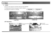
Basic 1. X RIGHT B/D Pull COF as shown in narrow. 3. X B/D : receiving LOGIC signal from CONTROL B/D and make ADDRESS PULSE(generates Address discharge)by ON/OFF operation, and supplies this waveform to COF(data) Signal part Power part X LEFT B/D Lift up lock as shown in narrow.
Basic 1. X RIGHT B/D Pull COF as shown in narrow. 3. X B/D : receiving LOGIC signal from CONTROL B/D and make ADDRESS PULSE(generates Address discharge)by ON/OFF operation, and supplies this waveform to COF(data) Signal part Power part X LEFT B/D Lift up lock as shown in narrow.
Service Manual
Page 67
Z sustain B/D : make SUSTAIN PULSE and ERASE PULSE that generates SUSTAIN discharge in arrow. Pull out Lock as shown in Lock part is supplied to panel through FPC(Z). *composed with IPM,FET,DIODE, electrolytic capacitor ,E/R coil. * IPM (Intelligent Power Module) E/R(Energy recovery) Separate the fixed Screw of Z-Board. 3. Basic 2. Condition in arrow. 12 this waveform is pulled Pull FPC Connector as shown in panel by receiving LOGIC signal from CONTROL B/D.
Z sustain B/D : make SUSTAIN PULSE and ERASE PULSE that generates SUSTAIN discharge in arrow. Pull out Lock as shown in Lock part is supplied to panel through FPC(Z). *composed with IPM,FET,DIODE, electrolytic capacitor ,E/R coil. * IPM (Intelligent Power Module) E/R(Energy recovery) Separate the fixed Screw of Z-Board. 3. Basic 2. Condition in arrow. 12 this waveform is pulled Pull FPC Connector as shown in panel by receiving LOGIC signal from CONTROL B/D.
Service Manual
Page 69
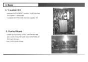
Control Board : creates signal processing (Contour noise,reduction ISM,..) and an order of many FET on/off of each DRIVER B/D with IPM,DIODE, electrolytic capacitor ,FET. 5. Basic 4. and supplies it Y DRIVER B/D. * Composed with R,G,B each 8bit input. * Use 3.3V/5V 2 kinds of power . 14 Y sustain B/D : generates SUSTAIN,RESET waveform, Vsc(SCAN)voltage. 3.
Control Board : creates signal processing (Contour noise,reduction ISM,..) and an order of many FET on/off of each DRIVER B/D with IPM,DIODE, electrolytic capacitor ,FET. 5. Basic 4. and supplies it Y DRIVER B/D. * Composed with R,G,B each 8bit input. * Use 3.3V/5V 2 kinds of power . 14 Y sustain B/D : generates SUSTAIN,RESET waveform, Vsc(SCAN)voltage. 3.
Service Manual
Page 71
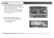
3. FFC (Flat Flexible Cable) : for Y B/D. These are having pattern on it * for Z B/D, there is no pattern , single-sided, and Beta type(all of this for connecting a Logic signal between B/D and B/D. *There is 0.5mm pitch,50pin type 1mm pitch ,30pin type. 16 One is single-sided, another is two type of copper surface). 8. FPC (Flexible Printed Circuit) : supply a driving waveform to PANEL by connecting a PAD electrode of PANEL with PCB(Y and Z). * there is double-side. Basic 7.
3. FFC (Flat Flexible Cable) : for Y B/D. These are having pattern on it * for Z B/D, there is no pattern , single-sided, and Beta type(all of this for connecting a Logic signal between B/D and B/D. *There is 0.5mm pitch,50pin type 1mm pitch ,30pin type. 16 One is single-sided, another is two type of copper surface). 8. FPC (Flexible Printed Circuit) : supply a driving waveform to PANEL by connecting a PAD electrode of PANEL with PCB(Y and Z). * there is double-side. Basic 7.

