
Service Manual
Page 36
Basic Operations & Circuit Description MODULE There are 5 pc.s PCBs including 1 pc. Keypad board, 1 pc. panel and 8 pc.s PCB including 2 pc.s Y/Z Sustainer board, 2 pc.s Y Drive board, 2 pc.s X (left and right) Extension PCB, 1 pc. Tuner/Audio board, 1 pc. Power board in the SET. SET There are 1 pc. L/R Speakers and 1 pc. Main (Video) board in the Module. Remote Control Receiver board, 1 pc. Control (Signal Input) and 1 pc.
Basic Operations & Circuit Description MODULE There are 5 pc.s PCBs including 1 pc. Keypad board, 1 pc. panel and 8 pc.s PCB including 2 pc.s Y/Z Sustainer board, 2 pc.s Y Drive board, 2 pc.s X (left and right) Extension PCB, 1 pc. Tuner/Audio board, 1 pc. Power board in the SET. SET There are 1 pc. L/R Speakers and 1 pc. Main (Video) board in the Module. Remote Control Receiver board, 1 pc. Control (Signal Input) and 1 pc.
Service Manual
Page 37
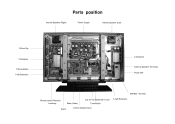
Parts position Internal Speaker (Right) Power Supply Internal Speaker (Left) Y-Drive Top Z-Sustainer Y-Sustainer External Speaker Terminals Y-Drive Bottom X left Extension Power SW EMI filter + AC Inlet only for the Model with Turner Main (Video) Stand Tuner/Audio X right Extension Remote control Receiver Local key Control (Signal Input)
Parts position Internal Speaker (Right) Power Supply Internal Speaker (Left) Y-Drive Top Z-Sustainer Y-Sustainer External Speaker Terminals Y-Drive Bottom X left Extension Power SW EMI filter + AC Inlet only for the Model with Turner Main (Video) Stand Tuner/Audio X right Extension Remote control Receiver Local key Control (Signal Input)

Service Manual
Page 40
... and RLY ON, Vs ON) to search available signal sources. Basic operation of Plasma Display 1. This time VIF will send ON Control signals to Power. If some abnormal signals are detected (for ON signals from Key Switch or Remote Receiver is detected, Micro Processor will send signals to display back light, OSD on...
... and RLY ON, Vs ON) to search available signal sources. Basic operation of Plasma Display 1. This time VIF will send ON Control signals to Power. If some abnormal signals are detected (for ON signals from Key Switch or Remote Receiver is detected, Micro Processor will send signals to display back light, OSD on...
Service Manual
Page 103
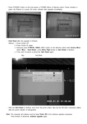
... color of Remote control, Power indicator is green, the Plasma is extinguished. Press STANDBY button on the Remote control enter factory Menu select "Misc.", "Hard Reset", press Menu Right button to Hard Reset is finished. Power Switch Off 2. If the function is abnormal, Hard Reset again. - Hard Reset - Note: The computer and plasma must be keep...
... color of Remote control, Power indicator is green, the Plasma is extinguished. Press STANDBY button on the Remote control enter factory Menu select "Misc.", "Hard Reset", press Menu Right button to Hard Reset is finished. Power Switch Off 2. If the function is abnormal, Hard Reset again. - Hard Reset - Note: The computer and plasma must be keep...
