
Service Manual
Page 2
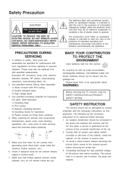
..., fusible resistors, etc.) 6. Examples: RF converters, tuner units, antenna selection switches, RF cables, noise-blocking capacitors, noise-blocking filters, etc. 2. Use specified insulating materials for fixing micro switches 4. SAFETY INSTRUCTION The service should not be connected in the literature accompanying the appliance. Completely discharge the high potential voltage of important operating...
..., fusible resistors, etc.) 6. Examples: RF converters, tuner units, antenna selection switches, RF cables, noise-blocking capacitors, noise-blocking filters, etc. 2. Use specified insulating materials for fixing micro switches 4. SAFETY INSTRUCTION The service should not be connected in the literature accompanying the appliance. Completely discharge the high potential voltage of important operating...
Service Manual
Page 42
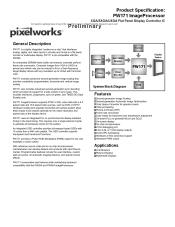
... or 10-bit display outputs !24-bit CPU Addressing !Hardware 2-Wire serial bus support !Hardware PWM output Applications !LCD Monitors !Plasma Displays !Multimedia Displays PW171 incorporates new features while maintaining backward compatibility with the PW264 and PW364 ImageProcessors. PW171 includes advanced second-generation image... 4:3 aspect ratio and 16:9 aspect ratio sources, such as DVD or HDTV. With reference source code and an on a fixed-frequency target display device with any resolution up screen, all necessary clocks for the system. An embedded SDRAM frame buffer and memory ...
... or 10-bit display outputs !24-bit CPU Addressing !Hardware 2-Wire serial bus support !Hardware PWM output Applications !LCD Monitors !Plasma Displays !Multimedia Displays PW171 incorporates new features while maintaining backward compatibility with the PW264 and PW364 ImageProcessors. PW171 includes advanced second-generation image... 4:3 aspect ratio and 16:9 aspect ratio sources, such as DVD or HDTV. With reference source code and an on a fixed-frequency target display device with any resolution up screen, all necessary clocks for the system. An embedded SDRAM frame buffer and memory ...
Service Manual
Page 67
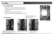
Basic 2. Pull out Lock as shown in arrow. 12 3. Z sustain B/D : make SUSTAIN PULSE and ERASE PULSE that generates SUSTAIN discharge in arrow. this waveform is pulled Pull FPC Connector as shown in panel by receiving LOGIC signal from CONTROL B/D. Condition in Lock part is supplied to panel through FPC(Z). *composed with IPM,FET,DIODE, electrolytic capacitor ,E/R coil. * IPM (Intelligent Power Module) E/R(Energy recovery) Separate the fixed Screw of Z-Board.
Basic 2. Pull out Lock as shown in arrow. 12 3. Z sustain B/D : make SUSTAIN PULSE and ERASE PULSE that generates SUSTAIN discharge in arrow. this waveform is pulled Pull FPC Connector as shown in panel by receiving LOGIC signal from CONTROL B/D. Condition in Lock part is supplied to panel through FPC(Z). *composed with IPM,FET,DIODE, electrolytic capacitor ,E/R coil. * IPM (Intelligent Power Module) E/R(Energy recovery) Separate the fixed Screw of Z-Board.
Service Manual
Page 90
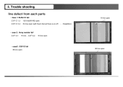
4. Trouble shooting. line defect from each parts • Case 1: Buffer IC fail COF IC 1,2 COF IC 3,4 192 line(96+96) open. 64 line open (with fixed interval there is on,off ...Repetition) 16 line open • case 2 : Array resistor fail COF IC1 16 line , COF IC2 16 line open • case3 : COF IC fail 96 line open. 96 line open
4. Trouble shooting. line defect from each parts • Case 1: Buffer IC fail COF IC 1,2 COF IC 3,4 192 line(96+96) open. 64 line open (with fixed interval there is on,off ...Repetition) 16 line open • case 2 : Array resistor fail COF IC1 16 line , COF IC2 16 line open • case3 : COF IC fail 96 line open. 96 line open