
User Guide
Page 5
... Monitoring DuraStor Using Front Bezel LEDs 4-2 Drive LEDs 4-3 Disk Drive Carrier Lite Pipes 4-5 One-Touch Annunciation 4-5 Enclosure SAF-TE Monitoring 4-9 Uploading SAF-TE Controller Card Firmware 4-11 5 Understanding and Maintaining Components Front Bezel 5-2 RAID Controllers (6320SS and ...Drives 5-10 Attaching a Disk Drive to a Drive Carrier 5-10 Replacing a Disk Drive 5-10 Power Supply Units 5-13 Replacing a PSU 5-14 Cooling Fan Module 5-15 Replacing the Cooling Fan Module 5-16 SAF-TE Disk I/O Card 5-17 SCSI I/O Card 5-19 Fibre Channel Host I/O Card (7320SS only) 5-20 Replacing an I/O Card...
... Monitoring DuraStor Using Front Bezel LEDs 4-2 Drive LEDs 4-3 Disk Drive Carrier Lite Pipes 4-5 One-Touch Annunciation 4-5 Enclosure SAF-TE Monitoring 4-9 Uploading SAF-TE Controller Card Firmware 4-11 5 Understanding and Maintaining Components Front Bezel 5-2 RAID Controllers (6320SS and ...Drives 5-10 Attaching a Disk Drive to a Drive Carrier 5-10 Replacing a Disk Drive 5-10 Power Supply Units 5-13 Replacing a PSU 5-14 Cooling Fan Module 5-15 Replacing the Cooling Fan Module 5-16 SAF-TE Disk I/O Card 5-17 SCSI I/O Card 5-19 Fibre Channel Host I/O Card (7320SS only) 5-20 Replacing an I/O Card...

User Guide
Page 11
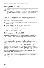
Introduction DuraStor 6320SS Figure 1-2 shows the components of LEDs) Power On LED Channel Status LED Power Supply Status LED Fan Status LED Alarm Reset Button 350-watt hot-pluggable independent power supplies Dual in-line 80-CFM hot swappable cooling fans SAFTE Disk I/O Card I/O Card (SCSI) Host I/O Card SAF-TE Service & VT-100 Ports Controller Cover Plate Figure 1-2 DuraStor 6320SS Storage Subsystem Optional Dual FC-to-SCSI RAID Controllers 1-3 Drive Status LEDs (left column of LEDs) Drive Activity LEDs (right column of the DuraStor 6320SS Storage Subsystem.
Introduction DuraStor 6320SS Figure 1-2 shows the components of LEDs) Power On LED Channel Status LED Power Supply Status LED Fan Status LED Alarm Reset Button 350-watt hot-pluggable independent power supplies Dual in-line 80-CFM hot swappable cooling fans SAFTE Disk I/O Card I/O Card (SCSI) Host I/O Card SAF-TE Service & VT-100 Ports Controller Cover Plate Figure 1-2 DuraStor 6320SS Storage Subsystem Optional Dual FC-to-SCSI RAID Controllers 1-3 Drive Status LEDs (left column of LEDs) Drive Activity LEDs (right column of the DuraStor 6320SS Storage Subsystem.
User Guide
Page 12
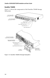
DuraStor 412R/6320SS/7320SS Installation and User's Guide DuraStor 7320SS Figure 1-3 shows the components of LEDs) Power On LED Channel Status LED Power Supply Status LED Fan Status LED Alarm Reset Button 350-watt hot-pluggable independent power supplies Dual in-line 80-CFM hot swappable cooling fans SAFTE Disk I/O Card I/O Card (SCSI) Host I/O Card... SAF-TE Service & VT-100 Ports Controller Cover Plate Figure 1-3 DuraStor 7320SS Storage Subsystem Optional Dual SCSI-to-SCSI RAID Controllers 1-4 Drive Status LEDs (left column of LEDs) Drive Activity ...
DuraStor 412R/6320SS/7320SS Installation and User's Guide DuraStor 7320SS Figure 1-3 shows the components of LEDs) Power On LED Channel Status LED Power Supply Status LED Fan Status LED Alarm Reset Button 350-watt hot-pluggable independent power supplies Dual in-line 80-CFM hot swappable cooling fans SAFTE Disk I/O Card I/O Card (SCSI) Host I/O Card... SAF-TE Service & VT-100 Ports Controller Cover Plate Figure 1-3 DuraStor 7320SS Storage Subsystem Optional Dual SCSI-to-SCSI RAID Controllers 1-4 Drive Status LEDs (left column of LEDs) Drive Activity ...
User Guide
Page 21
...TE disk I For the DuraStor 412R, see page 5-8) must be set up to create a single, continuous SCSI bus. In this mode, a single-bus module (see the next section, Basic Configuration - This module joins channel 1 and channel 2 together to 12 disk drives. Basic Configuration - In... single-bus module, which provides a storage solution with up the storage subsystem as a separate item from Adaptec. Configure your storage subsystem: I /O card assesses every disk drive (drives 1 through 12). DuraStor 6320SS on page 2-12. To set up as a single-bus or dual-bus JBOD (Just a Bunch Of...
...TE disk I For the DuraStor 412R, see page 5-8) must be set up to create a single, continuous SCSI bus. In this mode, a single-bus module (see the next section, Basic Configuration - This module joins channel 1 and channel 2 together to 12 disk drives. Basic Configuration - In... single-bus module, which provides a storage solution with up the storage subsystem as a separate item from Adaptec. Configure your storage subsystem: I /O card assesses every disk drive (drives 1 through 12). DuraStor 6320SS on page 2-12. To set up as a single-bus or dual-bus JBOD (Just a Bunch Of...

User Guide
Page 22
... Your Storage Subsystem CH 1 CH 2 Note: In these logical view diagrams, the numbers 1 to 12 represent disk drive slots and are used to indicate which drives are predetermined by the SCSI disk I/O card switch settings. Those IDs are connected to drives 1 through 12 and the channel 2 connector provides access to which channel. Figure 2-7 shows the...
... Your Storage Subsystem CH 1 CH 2 Note: In these logical view diagrams, the numbers 1 to 12 represent disk drive slots and are used to indicate which drives are predetermined by the SCSI disk I/O card switch settings. Those IDs are connected to drives 1 through 12 and the channel 2 connector provides access to which channel. Figure 2-7 shows the...

User Guide
Page 24
...Cabling Diagram - Refer to the Storage Manager Pro User's Guide or the Disk Array Administrator User's Guide for detailed instructions.) 6 Connect the SCSI data cable from the host system HBA to the SAF-TE Disk I/O card Channel connector as shown in the Controller 1 slot. (See Installing the Single Bus... Module and Cover Plate on page 5-9 for instructions on how to set up and configure disk arrays. 2-11 JBOD Dual-Bus Mode (DuraStor ...
...Cabling Diagram - Refer to the Storage Manager Pro User's Guide or the Disk Array Administrator User's Guide for detailed instructions.) 6 Connect the SCSI data cable from the host system HBA to the SAF-TE Disk I/O card Channel connector as shown in the Controller 1 slot. (See Installing the Single Bus... Module and Cover Plate on page 5-9 for instructions on how to set up and configure disk arrays. 2-11 JBOD Dual-Bus Mode (DuraStor ...

User Guide
Page 25
...SCSI IDs to fit your needs. There are two possible switch settings for the SAF-TE processors. Option 1 (DuraStor 6320SS) 2-12 DuraStor 6320SS The DuraStor 6320SS can add up to the DuraStor 6320SS storage subsystem. You may choose either Figure 2-13 or Figure 2-14. If you need to use more disk drives...on page 2-7. 2 Remove the SAF-TE disk I/O card installed in either setting to the drive slots, reserving IDs 6 and 7 for the RAID controller(s), and IDs 8 or 15 for this configuration. DuraStor 412R/6320SS/7320SS Installation and User's Guide Basic Configuration - This ...
...SCSI IDs to fit your needs. There are two possible switch settings for the SAF-TE processors. Option 1 (DuraStor 6320SS) 2-12 DuraStor 6320SS The DuraStor 6320SS can add up to the DuraStor 6320SS storage subsystem. You may choose either Figure 2-13 or Figure 2-14. If you need to use more disk drives...on page 2-7. 2 Remove the SAF-TE disk I/O card installed in either setting to the drive slots, reserving IDs 6 and 7 for the RAID controller(s), and IDs 8 or 15 for this configuration. DuraStor 412R/6320SS/7320SS Installation and User's Guide Basic Configuration - This ...

User Guide
Page 26
...solution with up to set up a basic 12-disk drive configuration: 1 Power OFF the storage subsystem. To set them as shown in the storage subsystem. (See Replacing an I/O Card on the card and set up and configure disk arrays. Setting Up Your Storage Subsystem SAF-TE ID = ...Slot 11 ID 12 Slot 12 ID 14 Drive IDs of the Drive Slots (Drive Channel Side) Figure 2-14 Dual-Bus Switch Setting - The switch settings assign specific SCSI IDs to the DuraStor 7320SS storage subsystem. Option 2 (DuraStor 6320SS) 4 Reinstall the SAF-TE disk I /O Card on page 5-21 for instructions.) 3 ...
...solution with up to set up a basic 12-disk drive configuration: 1 Power OFF the storage subsystem. To set them as shown in the storage subsystem. (See Replacing an I/O Card on the card and set up and configure disk arrays. Setting Up Your Storage Subsystem SAF-TE ID = ...Slot 11 ID 12 Slot 12 ID 14 Drive IDs of the Drive Slots (Drive Channel Side) Figure 2-14 Dual-Bus Switch Setting - The switch settings assign specific SCSI IDs to the DuraStor 7320SS storage subsystem. Option 2 (DuraStor 6320SS) 4 Reinstall the SAF-TE disk I /O Card on page 5-21 for instructions.) 3 ...

User Guide
Page 28
... for instructions. 3 Connect the SCSI data cables. a Connect the required SCSI data cable(s) to your host bus adapter(s) into the host system(s). Setting Up Your Storage Subsystem Cabling Your Storage System to the Host The last step of the DuraStor installation is properly configured to support this feature. DuraStor 6320SS). DuraStor 6320SS Note: This section provides cabling...
... for instructions. 3 Connect the SCSI data cables. a Connect the required SCSI data cable(s) to your host bus adapter(s) into the host system(s). Setting Up Your Storage Subsystem Cabling Your Storage System to the Host The last step of the DuraStor installation is properly configured to support this feature. DuraStor 6320SS). DuraStor 6320SS Note: This section provides cabling...

User Guide
Page 35
...ideal in Appendix C, Advanced Configurations and Cabling. DuraStor 412R/6320SS/7320SS Installation and User's Guide Basic Stand-Alone ...Dual-Port Topology - Host System #1 HBA 1 Controller FC Host Ports HOST I/O P1 RAID Controller FC1 Active T Disk CH1 P2 FC2 Active Disk CH2 T T Disk CH0 P4 Disk P3 CH3 Controller 1 T T= Location of internal termination Drive I/O Connectors Drives 7 - 12 Drives...SAFTE Disk I/O Chl 1 Chl 2 SCSI Disk I/O Chl 0 Chl 3 Host I /O Card Figure 2-25 Logical Diagram - This solution...
...ideal in Appendix C, Advanced Configurations and Cabling. DuraStor 412R/6320SS/7320SS Installation and User's Guide Basic Stand-Alone ...Dual-Port Topology - Host System #1 HBA 1 Controller FC Host Ports HOST I/O P1 RAID Controller FC1 Active T Disk CH1 P2 FC2 Active Disk CH2 T T Disk CH0 P4 Disk P3 CH3 Controller 1 T T= Location of internal termination Drive I/O Connectors Drives 7 - 12 Drives...SAFTE Disk I/O Chl 1 Chl 2 SCSI Disk I/O Chl 0 Chl 3 Host I /O Card Figure 2-25 Logical Diagram - This solution...

User Guide
Page 51
Monitoring DuraStor One-Touch Annunciation Example Figure 4-3 is an example of SCSI IDs. Note: SAF-TE switches 1 (A0) and 2 (A1) work in combinations to create a specific range of the switch settings, and the controller and bus configurations when the One-Touch Annunciation is accessed via the Reset button. SAF-TE Disk I/O Card Switch Settings A ARSS BDR 01D0 1DLM UP (1) 1 2 3 4 5 6 7 8 DOWN (0) Figure 4-3 Active-Active/Active-Passive Dual-Bus Example 4-7
Monitoring DuraStor One-Touch Annunciation Example Figure 4-3 is an example of SCSI IDs. Note: SAF-TE switches 1 (A0) and 2 (A1) work in combinations to create a specific range of the switch settings, and the controller and bus configurations when the One-Touch Annunciation is accessed via the Reset button. SAF-TE Disk I/O Card Switch Settings A ARSS BDR 01D0 1DLM UP (1) 1 2 3 4 5 6 7 8 DOWN (0) Figure 4-3 Active-Active/Active-Passive Dual-Bus Example 4-7

User Guide
Page 59
... RAID Controllers (6320SS and 7320SS only) Upgrading the Memory Module Replacing the Battery Configuring a Single-Bus Module Disk Drives Power Supply Units Cooling Fan Module SAF-TE Disk I/O Card SCSI I/O Card Fibre Channel Host I/O Card (7320SS only)... Optical SFP Transceiver (7320SS only) RS-232 Ports Replacing the Storage Subsystem 5-2 5-3 5-6 5-7 5-8 5-10 5-13 5-15 5-17 5-19 5-20 5-23 5-24 5-25 In this chapter, you will find detailed descriptions of the major DuraStor...
... RAID Controllers (6320SS and 7320SS only) Upgrading the Memory Module Replacing the Battery Configuring a Single-Bus Module Disk Drives Power Supply Units Cooling Fan Module SAF-TE Disk I/O Card SCSI I/O Card Fibre Channel Host I/O Card (7320SS only)... Optical SFP Transceiver (7320SS only) RS-232 Ports Replacing the Storage Subsystem 5-2 5-3 5-6 5-7 5-8 5-10 5-13 5-15 5-17 5-19 5-20 5-23 5-24 5-25 In this chapter, you will find detailed descriptions of the major DuraStor...

User Guide
Page 75
... Turning the Power Off on the front bezel changes to solid green to the disk drive channels for daisy-chain requirements. SAF-TE Disk I/O Card Warning: The SAF-TE disk I /O card (Figure 5-14) provides environmental and system status monitoring, and connectivity to indicate normal ...storage subsystem temperature and continually report conditions to remove or replace this card. The SAF-TE disk I /O card is not hot-swappable. Inspect the module for setting SCSI IDs, VT-100 communication protocols, and drive spin-up options. Understanding and Maintaining Components 3 Remove the replacement ...
... Turning the Power Off on the front bezel changes to solid green to the disk drive channels for daisy-chain requirements. SAF-TE Disk I/O Card Warning: The SAF-TE disk I /O card (Figure 5-14) provides environmental and system status monitoring, and connectivity to indicate normal ...storage subsystem temperature and continually report conditions to remove or replace this card. The SAF-TE disk I /O card is not hot-swappable. Inspect the module for setting SCSI IDs, VT-100 communication protocols, and drive spin-up options. Understanding and Maintaining Components 3 Remove the replacement ...
User Guide
Page 76
DuraStor 412R/6320SS/7320SS Installation and User's Guide At power-on the drive mid-plane circuit board. In each of the supported configurations, all DuraStor 412R enclosures appear at the end of the fact that the SAF-TE Disk I/O card is flash upgradeable using the SAF-TE RS-232 service ... in the last enclosure's SAF-TE disk I In JBOD single-bus mode, the Channel 1 connector provides SCSI bus access to the drives in the daisy-chained DuraStor storage subsystems. The connectors are possible: I /O card slots at the same time. These jumpers allow the automatic termination to the disk...
DuraStor 412R/6320SS/7320SS Installation and User's Guide At power-on the drive mid-plane circuit board. In each of the supported configurations, all DuraStor 412R enclosures appear at the end of the fact that the SAF-TE Disk I/O card is flash upgradeable using the SAF-TE RS-232 service ... in the last enclosure's SAF-TE disk I In JBOD single-bus mode, the Channel 1 connector provides SCSI bus access to the drives in the daisy-chained DuraStor storage subsystems. The connectors are possible: I /O card slots at the same time. These jumpers allow the automatic termination to the disk...

User Guide
Page 77
... card. SCSI I/O Card Warning: The SCSI I /O Card on page 5-21. Understanding and Maintaining Components When the RAID controllers are installed, the SCSI connectors on the SAF-TE disk I /O cards are configured with automatic termination and do not 5-19 however, their settings do not require any external terminators. You must power down the storage subsystem to additional DuraStor 412R drive...
... card. SCSI I/O Card Warning: The SCSI I /O Card on page 5-21. Understanding and Maintaining Components When the RAID controllers are installed, the SCSI connectors on the SAF-TE disk I /O cards are configured with automatic termination and do not 5-19 however, their settings do not require any external terminators. You must power down the storage subsystem to additional DuraStor 412R drive...

User Guide
Page 87
...drives connected to the HBA channels are properly connected. Probable Cause Termination or SCSI ID conflict. I If the enclosure is the daisy-chained enclosure, check the I /O card. Troubleshooting Common SCSI Bus Problems SCSI Bus problems can usually be attributed to cabling issues or a faulty SAF-TE disk I /O card... jumper settings in identifying the suspect component. I Check SCSI ID assignments. I Check that the SCSI connectors are displayed during boot. Termination or SCSI ID conflict. Solution Check the Host ID and proper...
...drives connected to the HBA channels are properly connected. Probable Cause Termination or SCSI ID conflict. I If the enclosure is the daisy-chained enclosure, check the I /O card. Troubleshooting Common SCSI Bus Problems SCSI Bus problems can usually be attributed to cabling issues or a faulty SAF-TE disk I /O card... jumper settings in identifying the suspect component. I Check SCSI ID assignments. I Check that the SCSI connectors are displayed during boot. Termination or SCSI ID conflict. Solution Check the Host ID and proper...

User Guide
Page 88
... disk I If all the disk drives on the SCSI bus, you have daisychained storage subsystems connected on one bus are offline, start with the daisy-chain storage subsystem. DuraStor 412R/6320SS/7320SS Installation and User's Guide Symptom SCSI Bus hangs, SCSI Bus excessively retries, and/or drives drop offline. I Faulty SAF-TE disk I /O card. Disconnect the data cable.
... disk I If all the disk drives on the SCSI bus, you have daisychained storage subsystems connected on one bus are offline, start with the daisy-chain storage subsystem. DuraStor 412R/6320SS/7320SS Installation and User's Guide Symptom SCSI Bus hangs, SCSI Bus excessively retries, and/or drives drop offline. I Faulty SAF-TE disk I /O card. Disconnect the data cable.

User Guide
Page 89
... adapter. Troubleshooting Probable Cause I Faulty SAF-TE disk I/O card (JBOD or Daisy-chained enclosure) or host I /O cards installed in a normal state. There are two host I /O card (continued). I After the faulty card is indicated by the disk drives coming back online. I Replace the SAF-TE disk I/O card or host I /O card, noting the SCSI bus and drives remain in RAID configurations.
... adapter. Troubleshooting Probable Cause I Faulty SAF-TE disk I/O card (JBOD or Daisy-chained enclosure) or host I /O cards installed in a normal state. There are two host I /O card (continued). I After the faulty card is indicated by the disk drives coming back online. I Replace the SAF-TE disk I/O card or host I /O card, noting the SCSI bus and drives remain in RAID configurations.

User Guide
Page 144
...should not be confused with the disk drive SCSI IDs. Single-Bus Mode Note: In Figure C-1, the drive slots are connected to create a single continuous SCSI bus. C-2 Figure C-2 Single-Bus JBOD Switch Setting 3 Reinstall the SAF-TE disk I /O Card on page 5-21 for detailed instructions....together to which drives are used to indicate which channel. There is one switch setting for detailed instructions. 2 Locate the switches on page 5-21 for both enclosures. DuraStor 412R/6320SS/7320SS Installation and User's Guide Controller 1 slot. See Replacing an I/O Card on each card and set ...
...should not be confused with the disk drive SCSI IDs. Single-Bus Mode Note: In Figure C-1, the drive slots are connected to create a single continuous SCSI bus. C-2 Figure C-2 Single-Bus JBOD Switch Setting 3 Reinstall the SAF-TE disk I /O Card on page 5-21 for detailed instructions....together to which drives are used to indicate which channel. There is one switch setting for detailed instructions. 2 Locate the switches on page 5-21 for both enclosures. DuraStor 412R/6320SS/7320SS Installation and User's Guide Controller 1 slot. See Replacing an I/O Card on each card and set ...

User Guide
Page 145
... Fans SAFTE Disk I/O Chl 1 Chl 2 Ctlr 1 SAF-TE Ctlr 2 Single-Bus Mode Single Bus Module SCSI Data Cable Power Power Supply Supply Cooling Fans SAFTE Disk I /O card Channel 1 connectors on page 2-7. C-3 See Installing the Single Bus Module and Cover Plate on page 5-9 for detailed... instructions. 5 Connect a SCSI data cable from the host system HBA(s) to the SAF-TE disk I /O Chl 1 Chl 2 ...
... Fans SAFTE Disk I/O Chl 1 Chl 2 Ctlr 1 SAF-TE Ctlr 2 Single-Bus Mode Single Bus Module SCSI Data Cable Power Power Supply Supply Cooling Fans SAFTE Disk I /O card Channel 1 connectors on page 2-7. C-3 See Installing the Single Bus Module and Cover Plate on page 5-9 for detailed... instructions. 5 Connect a SCSI data cable from the host system HBA(s) to the SAF-TE disk I /O Chl 1 Chl 2 ...