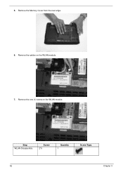
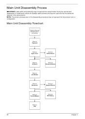
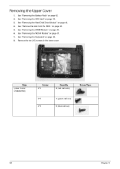
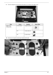
Acer Ferrari One 200 Netbook Series Generic User Guide
Page 6
Do not use any charger or battery that which could affect performance. Do not pierce, open or disassemble the battery. If the battery leaks and you carry a spare battery in a humid, wet or corrosive environment. When the operation time becomes noticeably ...present a risk of used batteries. Do not dispose of the battery, charging will be susceptible to local regulations. Please recycle when possible. Do not disassemble or dispose of a new battery is fully charged. vi Guidelines for example, when you come into contact with the leaked fluids, rinse thoroughly with water...
Acer Ferrari One 200 Service Guide
Page 7
...34 Removing BIOS Passwords 35 Miscellaneous Utilities 36 Machine Disassembly and Replacement 39 Disassembly Requirements 39 Related Information 39 Replacement Requirements 39 General Information 39 Pre-disassembly Instructions 39 Disassembly Process 40 External Module Disassembly Process 40 External Modules Disassembly Flowchart 41 Removing the Battery Pack 42 Removing ...Removing the 3G Module 46 Removing the DIMM Module 49 Removing the WLAN Module 51 Main Unit Disassembly Process 54 Main Unit Disassembly Flowchart 54 Removing the Keyboard 56 Removing the Upper Cover 58 vii
Acer Ferrari One 200 Service Guide
Page 8
... Mainboard 71 Removing the Thermal Module 73 Removing the CPU 75 Removing the RTC Battery 75 Removing the Speaker Modules 77 LCD Module Disassembly Process 79 LCD Module Disassembly Flowchart 79 Removing the LCD Bezel 81 Removing the Camera Board 83 Removing the LCD Panel 84 Removing the LCD Brackets 86 Removing...
Acer Ferrari One 200 Service Guide
Page 49
... replaced in the same position. Turn off the power to be applied during the replacement and reassembly process. Disassembly Requirements To disassemble the computer, you do the following tools: • Wrist grounding strap and conductive mat for preventing electrostatic ... represent the final product color or configuration. General Information Pre-disassembly Instructions Before proceeding with the corresponding components to avoid mismatch when putting back the components. Chapter 3 Machine Disassembly and Replacement This chapter contains step-by Holdtite Adhesives LTD. NOTE...
Acer Ferrari One 200 Service Guide
Page 50
...avoid damage to remove the Mainboard, you must first remove the Keyboard, and LCD Module then disassemble the inside assembly frame in the succeeding disassembly sections illustrate the entire disassembly sequence. For example, if you want to any of the hardware components. Main Screw List...003 M2*5 16 86.TG607.004 M2*8 5 86.FRC07.001 M2-0.4.5*2 FH 2 86.W4107.002 External Module Disassembly Process NOTE: The product previews seen in the disassembly procedures may not represent the final product color or configuration. 40 Chapter 3 Remove the battery pack. Unplug the ...
Acer Ferrari One 200 Service Guide
Page 51
External Modules Disassembly Flowchart Turn off system and peripherals power Disconnect power and signal cables from system Remove Dummy Card Remove Battery Remove SIM Card Remove Lower Covers Remove HDD Remove DIMM Remove WLAN Board Remove 3G Board Screw List Step HDD Module 3G Module WLAN Module Screw M3*3.5(silver) M2*4 M2*5 Quantity 4 1 1 Part No. 86.TPK07.001 86.W0107.003 86.TG607.004 Chapter 3 41
Acer Ferrari One 200 Service Guide
Page 56
Remove the rails from the HDD. 8. See "Removing the Battery Pack" on page 42. 46 Chapter 3 Remove the four (4) screws of the HDD rails. Screw Type. Remove the HDD cable from the HDD. Step HDD Disassembly Screw 3*3.5 (silver) Quantity 4 9. Removing the 3G Module 1. 7.
Acer Ferrari One 200 Service Guide
Page 58
Screw Type. 48 Chapter 3 Step 3G Disassembly Screw 2*4 Quantity 1 6. 5. Remove the 3G module. Remove the one (1) screw from the 3G module.
Acer Ferrari One 200 Service Guide
Page 62
5. Step WLAN Disassembly Screw 2*5 Quantity 1 Screw Type. 52 Chapter 3 Remove the cables on the WLAN module. Remove the Memory Cover from the rear edge. 6. Remove the one (1) screw on the WLAN module. 7.
Acer Ferrari One 200 Service Guide
Page 64
NOTE: The product previews seen in the same position. Main Unit Disassembly Flowchart Remove External Modules before proceeding Remove Keyboard Remove Upper Cover Remove Button Board Remove I/O Board Remove Bluetooth Module Remove LCD Module Remove ...3 During the removal and replacement of components, ensure all available cable channels and clips are used and that the cables are replaced in the disassembly procedures may not represent the actual model. Main Unit Disassembly Process IMPORTANT: Cable paths and positioning may not represent the final product color or configuration.
Acer Ferrari One 200 Service Guide
Page 68
See "Removing the Battery Pack" on page 44. 4. See "Removing the Hard Disk Drive Module" on page 42. 2. See "Removing the Keyboard" on page 51. 7. See "Removing the WLAN Module" on page 56. 8. Remove the ten (10) screws in the lower cover Step Lower Cover Disassembly Screw 2*3 Quantity 4 (red call outs) Screw Type. 2*5 1 (green call out) 2*8 5 (blue call out) 58 Chapter 3 on page 49. 6. See "Removing the DIMM Module" on page 46. 5. See "Removing the SIM Card" on page 43. 3. See "Remove the rails from the HDD." Removing the Upper Cover 1.
Acer Ferrari One 200 Service Guide
Page 69
Screw Type. Unlock the I/O board to main board cable at both ends. Chapter 3 59 9. Turn the computer over and remove the eleven (11) screws in the upper cover. Step Upper Cover Disassembly Screw 2.0*2.5 Silver Quantity 1 (green call out) 2*3 1 (blue call out) 2*5 9 (red call out) 10.
Acer Ferrari One 200 Service Guide
Page 73
Remove the two (2) screws of the button board. Step Button Board Disassembly Screw M2-0.4*2 Quantity 2 Screw Type. Pull the button board cable away from the adhesive. 6. Chapter 3 63 5. Remove the button board cable. 7.
Acer Ferrari One 200 Service Guide
Page 77
Disconnect the DC power cable from the I /O board. Step IO Board Disassembly Screw 2*5 Quantity 1 Screw Type. Remove the one (1) screw in the I /O board. 7. Chapter 3 67 5. Remove the tape and lift the DC cable out of the cable guide. 6.
Acer Ferrari One 200 Service Guide
Page 80
NOTE: Lay the LCD down . Pull the antenna cables free of the chassis, threading the antenna cables through from the left and right hinges of the LCD module. Lift away the LCD module and lay it down on a clear smooth surface to prevent damage. 7. Remove the LCD module completely. 70 Chapter 3 5. Step LCD Disassembly Screw 2*5 Quantity 2 Screw Type. 6. Remove the two (2) screws from the bottom side.. 8.
Acer Ferrari One 200 Service Guide
Page 81
Removing the Mainboard 1. See "Removing the Upper Cover" on page 65. 3. See "Removing the Bluetooth Module" on page 58. 2. Remove the one (1) screw in the main board. See "Removing the I/O Board" on page 69. 5. Chapter 3 71 See "Removing the LCD Module" on page 66. 4. Disconnect the speaker connector. 6. Step Main Board Disassembly Screw 2*3 Quantity 1 Screw Type.
Acer Ferrari One 200 Service Guide
Page 83
Removing the Thermal Module 1. Remove the three (3) screws (red call outs) and loosen the two (2) captive screws (blue call outs). Disconnect fan connector. 3. Chapter 3 73 Step Thermal Module Disassembly Screw 2*3 Quantity 3 Screw Type. See "Removing the Mainboard" on page 71. 2.
Acer Ferrari One 200 Service Guide
Page 87
Remove the three (3) screws securing the Speakers to the lower cover. Remove the tape from the speaker cable. Step Speaker Module Disassembly Screw 2*3 Quantity 3 3. Chapter 3 77 Screw Type. Removing the Speaker Modules 1. See "Removing the Mainboard" on page 71. 2.
Acer Ferrari One 200 Service Guide
Page 89
... IMPORTANT: Cable paths and positioning may not represent the final product color or configuration. LCD Module Disassembly Flowchart Remove LCD Module from Main Unit before proceeding Remove LCD Module Bezel Remove Camera Module Detach Microphone Remove LCD Panel ...Remove LCD FPC Cable Remove Antennas Remove LCD Brackets Screw List Step LCD Bezel Disassembly LCD Panel Disassembly Screw 2*5 2*3 Quantity 2 4 Part No. 86.TG607.004 86.S0207.001 Chapter 3 79 During the removal and replacement of components, ensure ...
Acer Ferrari One 200 Service Guide
Page 91
Removing the LCD Bezel 1. Chapter 3 81 Remove the two (2) screw covers. 3. Step Bezel Disassembly Screw 2*5 Quantity 2 Screw Type. Remove the two (2) screws. See "Removing the LCD Module" on page 69. 2.