

Service Guide
Page 6
... 4 Bottom View 5 Outlook View 6 Front Open View 6 Front Panel 7 Left Panel 8 Right Panel 9 Rear Panel 10 Bottom Panel 11 Indicators 12 Using the Keyboard 13 Lock Keys 13 Embedded Numeric Keypad 14 Windows Keys 15 Hot Keys 16 The Euro Symbol 18 Launch Keys 19 Touchpad 20 Touchpad Basics... Module 51 Removing the Wireless LAN Card 51 Removing the LCD Module 52 Disassembling the Main Unit 53 Remove the function key board and the keyboard 53 Separate the main unit into the logic upper and the logic lower assembly . . . . .53 Disassembling the logic upper assembly 54 ...
... 4 Bottom View 5 Outlook View 6 Front Open View 6 Front Panel 7 Left Panel 8 Right Panel 9 Rear Panel 10 Bottom Panel 11 Indicators 12 Using the Keyboard 13 Lock Keys 13 Embedded Numeric Keypad 14 Windows Keys 15 Hot Keys 16 The Euro Symbol 18 Launch Keys 19 Touchpad 20 Touchpad Basics... Module 51 Removing the Wireless LAN Card 51 Removing the LCD Module 52 Disassembling the Main Unit 53 Remove the function key board and the keyboard 53 Separate the main unit into the logic upper and the logic lower assembly . . . . .53 Disassembling the logic upper assembly 54 ...
Service Guide
Page 7
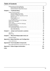
...Optical Drive Module 59 Chapter 4 Troubleshooting 61 System Check Procedures 62 External Diskette Drive Check 62 External CD-ROM Drive Check 62 Keyboard or Auxiliary Input Device Check 62 Memory check 63 Power System Check 63 Touchpad check 64 Power-On Self-Test (POST) ...Top View 85 Bottom View 86 Chapter 6 FRU (Field Replaceable Unit) List 87 Exploded Diagram 88 Appendix A Model Definition and Configuration 96 Ferrari 3200 Series 96 Appendix B Test Compatible Components 97 Microsoft® Windows® XP Home Environment Test 98 Appendix C Online Support Information ...
...Optical Drive Module 59 Chapter 4 Troubleshooting 61 System Check Procedures 62 External Diskette Drive Check 62 External CD-ROM Drive Check 62 Keyboard or Auxiliary Input Device Check 62 Memory check 63 Power System Check 63 Touchpad check 64 Power-On Self-Test (POST) ...Top View 85 Bottom View 86 Chapter 6 FRU (Field Replaceable Unit) List 87 Exploded Diagram 88 Appendix A Model Definition and Configuration 96 Ferrari 3200 Series 96 Appendix B Test Compatible Components 97 Microsoft® Windows® XP Home Environment Test 98 Appendix C Online Support Information ...

Service Guide
Page 9
... Device T 84-/85-/88-key Windows keyboard T Sleek, smooth and stylish design T Acer FinTouch full-sized curved keyboard T Ergonomically-centered touchpad pointing device with four-way scroll button Expansion T T One type II CardBus PC Card slot Upgradeable memory I/O Ports T T T T T T T T T T T T T T T One Card bus type ... 2.0 ports One IEEE 1394 port One S-video (NTSC/PAL) output port 4-in-1 Card Reader (Manufacture optional) FIR (Fast Infred) port 100-pin expansion port supporting Acer EasyPort or I/O port replicator 2 Chapter 1
... Device T 84-/85-/88-key Windows keyboard T Sleek, smooth and stylish design T Acer FinTouch full-sized curved keyboard T Ergonomically-centered touchpad pointing device with four-way scroll button Expansion T T One type II CardBus PC Card slot Upgradeable memory I/O Ports T T T T T T T T T T T T T T T One Card bus type ... 2.0 ports One IEEE 1394 port One S-video (NTSC/PAL) output port 4-in-1 Card Reader (Manufacture optional) FIR (Fast Infred) port 100-pin expansion port supporting Acer EasyPort or I/O port replicator 2 Chapter 1

Service Guide
Page 13
... five buttons. the center button serves as you use the computer. Outlook View A general introduction of ports allow you to show the status of the keyboard are designated as P1, P2, P3, E-mail button and Web browser button. Turns on and off to connect peripheral devices, as a 4-way scroll button. The...
... five buttons. the center button serves as you use the computer. Outlook View A general introduction of ports allow you to show the status of the keyboard are designated as P1, P2, P3, E-mail button and Web browser button. Turns on and off to connect peripheral devices, as a 4-way scroll button. The...

Service Guide
Page 20
...or down when you press w and y respectively. When Num Lock is on and off by pressing the Fn + F11 keys simultaneously. Using the Keyboard The full-sized keyboardincludes an embedded numeric keypad, separate cursor keys, two Windows keys and twelve function keys. Chapter 1 13 justmanuals.com Toggle on... the left of the keyboard. Toggle on and off by pressing the Caps Lock key on and off . When Scroll Lock is on , all alphabetic characters are typed ...
...or down when you press w and y respectively. When Num Lock is on and off by pressing the Fn + F11 keys simultaneously. Using the Keyboard The full-sized keyboardincludes an embedded numeric keypad, separate cursor keys, two Windows keys and twelve function keys. Chapter 1 13 justmanuals.com Toggle on... the left of the keyboard. Toggle on and off by pressing the Caps Lock key on and off . When Scroll Lock is on , all alphabetic characters are typed ...

Service Guide
Page 21
...normal keypad manner. Desired Access Num Lock On Number keys on embedded Type numbers in a normal manner. 14 Chapter 1 To simplify the keyboard legend, cursor-control key symbols are not printed on the upper right corner of the keycaps. It is indicated by small characters located ...on the keys. Main keyboard keys Hold Fn while typing letters on embedded keypad Hold j while using cursorcontrol keys. Cursor-control keys on embedded keypad. Embedded Numeric...
...normal keypad manner. Desired Access Num Lock On Number keys on embedded Type numbers in a normal manner. 14 Chapter 1 To simplify the keyboard legend, cursor-control key symbols are not printed on the upper right corner of the keycaps. It is indicated by small characters located ...on the keys. Main keyboard keys Hold Fn while typing letters on embedded keypad Hold j while using cursorcontrol keys. Cursor-control keys on embedded keypad. Embedded Numeric...

Service Guide
Page 22
Chapter 1 15 justmanuals.com Below are a few examples: + Tab (Activates next taskbar button) + E (Explores My Computer) + F (Finds Document) + M (Minimizes All) j + Windows logo key + M (Undoes Minimize All) + R (Displays the Run... Windows Keys The keyboard has two keys that perform Windows-specific functions. Key Windows logo key Application key Icon Description Start button. Combinations with this key perform special functions. dialog box) Opens a context menu (same as a right-click).
Chapter 1 15 justmanuals.com Below are a few examples: + Tab (Activates next taskbar button) + E (Explores My Computer) + F (Finds Document) + M (Minimizes All) j + Windows logo key + M (Undoes Minimize All) + R (Displays the Run... Windows Keys The keyboard has two keys that perform Windows-specific functions. Key Windows logo key Application key Icon Description Start button. Combinations with this key perform special functions. dialog box) Opens a context menu (same as a right-click).

Service Guide
Page 25
...and click on OK. Click on Details. 4. Locate the Euro symbol on OK. 5. To verify the keyboard type in Windows XP, follow the steps below: 1. Verify that the keyboard layout used for "En English (United States)" is set to www.microsoft.com/ typography/faq/faq12.htm ... Please refer to United States-International. then select United States-International and click on your keyboard. 2. To type the Euro symbol: 1. Open a text editor or word processor. 3. NOTE: For US keyboard users: The keyboard layout is set when you can type the Euro symbol on Regional and Language Options. 3....
...and click on OK. Click on Details. 4. Locate the Euro symbol on OK. 5. To verify the keyboard type in Windows XP, follow the steps below: 1. Verify that the keyboard layout used for "En English (United States)" is set to www.microsoft.com/ typography/faq/faq12.htm ... Please refer to United States-International. then select United States-International and click on your keyboard. 2. To type the Euro symbol: 1. Open a text editor or word processor. 3. NOTE: For US keyboard users: The keyboard layout is set when you can type the Euro symbol on Regional and Language Options. 3....

Service Guide
Page 26
... Mail Web browser P1 P2 Default application Email application Internet browser application User-programmable User-programmable E-mail Detection Click right button at the top of keyboard are five buttons. Password and POP3 Server in User Name. Chapter 1 19 justmanuals.com Launch Keys Located at the Launch Manager icon on the taskbar...
... Mail Web browser P1 P2 Default application Email application Internet browser application User-programmable User-programmable E-mail Detection Click right button at the top of keyboard are five buttons. Password and POP3 Server in User Name. Chapter 1 19 justmanuals.com Launch Keys Located at the Launch Manager icon on the taskbar...

Service Guide
Page 29
... combinations Phneoix Specification Flash ROM 512KB PLCC ACPI 1.0b, PC Card 95, SM BIOS 2.3, EPP/IEEE 1284, ECP/IEEE 1284 1.7 & 1.9, PCI 2.2, PnP 1.0a, DMI 2.0, PS/2 keyboard and mouse, USB 2.0, VGA BIOS, CD-ROM bootable, IEEE 1394 Set by setup manual Built-in CPU 512KB Always enabled Always enabled Fixed in write...
... combinations Phneoix Specification Flash ROM 512KB PLCC ACPI 1.0b, PC Card 95, SM BIOS 2.3, EPP/IEEE 1284, ECP/IEEE 1284 1.7 & 1.9, PCI 2.2, PnP 1.0a, DMI 2.0, PS/2 keyboard and mouse, USB 2.0, VGA BIOS, CD-ROM bootable, IEEE 1394 Set by setup manual Built-in CPU 512KB Always enabled Always enabled Fixed in write...
Service Guide
Page 34
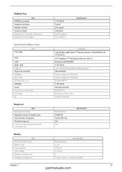
... embedded USB controller NS PC87393 South bridge/VIA VT8235CE South bridge/VIA VT8235CE BCM4306KFB TI PCI4510 RealTek ALC202 M220V0315 Synaptics TM41P-353 Vishay TFU6102F Keyboard Item Keyboard controller Keyboard vendor & model name Total number of slots Access location Supports ZV (Zoomed Video) port Supports 32 bit CardBus TI PCI4510 Type-II One type... PCMCIA Audio Four-in parallel Chapter 1 27 justmanuals.com PCMCIA Port Item PCMCIA controller Supports card type Number of keypads Windows logo key Internal & external keyboard work simultaneously NS 87570 C4 DARFON 84-/85-/88-
... embedded USB controller NS PC87393 South bridge/VIA VT8235CE South bridge/VIA VT8235CE BCM4306KFB TI PCI4510 RealTek ALC202 M220V0315 Synaptics TM41P-353 Vishay TFU6102F Keyboard Item Keyboard controller Keyboard vendor & model name Total number of slots Access location Supports ZV (Zoomed Video) port Supports 32 bit CardBus TI PCI4510 Type-II One type... PCMCIA Audio Four-in parallel Chapter 1 27 justmanuals.com PCMCIA Port Item PCMCIA controller Supports card type Number of keypads Windows logo key Internal & external keyboard work simultaneously NS 87570 C4 DARFON 84-/85-/88-

Service Guide
Page 36
.... 2.System standby/ Hibernation timer expires and system is in touchpad, and an external PS/2 pointing device are turned off the whole system. Display Standby Mode Keyboard, built-in standby mode. (spindle turned-off T Hard disk drive is not ready to Disk (S4) Power Management OS initiated shutdown. Hard Disk Standby Mode...
.... 2.System standby/ Hibernation timer expires and system is in touchpad, and an external PS/2 pointing device are turned off the whole system. Display Standby Mode Keyboard, built-in standby mode. (spindle turned-off T Hard disk drive is not ready to Disk (S4) Power Management OS initiated shutdown. Hard Disk Standby Mode...
Service Guide
Page 54
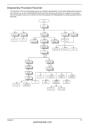
Start Battery Hx2 HDD Door Hx2 Dimm Door HDD Module Memory Hx2 Mx3 Keyboard Ox4 Middle Cover Sx4 LCD Module Hx3 Function Key Board Hx2 PCI Door ODD Module Wireless LAN Card Touchpad Main Unit Assembly Front Bezel Sx19 ... (FFC) Logic Lower Assembly Ax4 Hx1 Hx1 Main Board CPU Dimm Dx3 4-in that need to remove the system board, you must first remove the keyboard, then disassemble the inside assembly frame in -1 Card Rearder Fx2 Smart Card Reader Hx1 Top Cover Shielding Tx2 HDD Bracket Hx2 Modem/ Bluetooth Combo Card...
Start Battery Hx2 HDD Door Hx2 Dimm Door HDD Module Memory Hx2 Mx3 Keyboard Ox4 Middle Cover Sx4 LCD Module Hx3 Function Key Board Hx2 PCI Door ODD Module Wireless LAN Card Touchpad Main Unit Assembly Front Bezel Sx19 ... (FFC) Logic Lower Assembly Ax4 Hx1 Hx1 Main Board CPU Dimm Dx3 4-in that need to remove the system board, you must first remove the keyboard, then disassemble the inside assembly frame in -1 Card Rearder Fx2 Smart Card Reader Hx1 Top Cover Shielding Tx2 HDD Bracket Hx2 Modem/ Bluetooth Combo Card...
Service Guide
Page 60
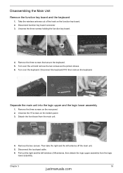
...2. Disconnect the touchpad cable. 6. Disconnect function key board connector 3. Unscrew the three screws holding the function key board. 4. Turn over the keyboard. Then take the right and the left wireless LAN antenna, then detach the logic upper assembly from the main unit. 4. Turn over the...Chapter 3 53 justmanuals.com Remove the three screws on the bottom panel. 3. Disassembling the Main Unit Remove the function key board and the keyboard 1. Take the wireless antenna out of the hook on the function key board. 2. Detach the front bezel from the logic lower assembly....
...2. Disconnect the touchpad cable. 6. Disconnect function key board connector 3. Unscrew the three screws holding the function key board. 4. Turn over the keyboard. Then take the right and the left wireless LAN antenna, then detach the logic upper assembly from the main unit. 4. Turn over the...Chapter 3 53 justmanuals.com Remove the three screws on the bottom panel. 3. Disassembling the Main Unit Remove the function key board and the keyboard 1. Take the wireless antenna out of the hook on the function key board. 2. Detach the front bezel from the logic lower assembly....
Service Guide
Page 69
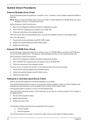
...the problem to fail. If an error occurs, reconnect the connector on the system board. Replace the main board. If the internal keyboard does not work , reconnect the cable connector and repeat the failing operation. 62 Chapter 4 Make sure that the CD-ROM does not... the diagnostics diskette and start the diagnostics program. 2. The following auxiliary input devices are supported by this computer: T Numeric keypad T External keyboard If any label attached to be tested. NOTE: Make sure that the flexible cable extending from the diagnostics diskette and start the diagnostics program....
...the problem to fail. If an error occurs, reconnect the connector on the system board. Replace the main board. If the internal keyboard does not work , reconnect the cable connector and repeat the failing operation. 62 Chapter 4 Make sure that the CD-ROM does not... the diagnostics diskette and start the diagnostics program. 2. The following auxiliary input devices are supported by this computer: T Numeric keypad T External keyboard If any label attached to be tested. NOTE: Make sure that the flexible cable extending from the diagnostics diskette and start the diagnostics program....
Service Guide
Page 73
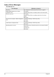
Default configuration used Invalid System Configuration Data Operating system not found FRU/Action in Sequence See ""Keyboard or Auxiliary Input Device Check" on page 62 RTC battery Run BIOS Setup Utility to reconfigure system time, then reboot system. RTC battery Run BIOS ...
Default configuration used Invalid System Configuration Data Operating system not found FRU/Action in Sequence See ""Keyboard or Auxiliary Input Device Check" on page 62 RTC battery Run BIOS Setup Utility to reconfigure system time, then reboot system. RTC battery Run BIOS ...

Service Guide
Page 75
...Load alternate registers with initial POST values Restore CPU control word during warm boot Initialize PCI Bus Mastering devices Initialize keyboard controller BIOS ROM checksum Initialize cache before memory autosize 8254 timer initialization 8237 DMA controller initialization Reset Programmable Interrupt ...Controller Test DRAM refresh Test 8742 Keyboard Controller Set ES segment register to 4 GB Enable A20 line Autosize DRAM Initialize POST Memory Manager Clear 215 KB...
...Load alternate registers with initial POST values Restore CPU control word during warm boot Initialize PCI Bus Mastering devices Initialize keyboard controller BIOS ROM checksum Initialize cache before memory autosize 8254 timer initialization 8237 DMA controller initialization Reset Programmable Interrupt ...Controller Test DRAM refresh Test 8742 Keyboard Controller Set ES segment register to 4 GB Enable A20 line Autosize DRAM Initialize POST Memory Manager Clear 215 KB...

Service Guide
Page 76
... system QuietBoot start (optional) Shadow video BIOS ROM Display BIOS copyright notice Display CPU type and speed Initialize EISA board Test keyboard Set key click if enabled Test for unexpected interrupts Initialize POST display service Display prompt "Press F2 to enter SETUP" Disable... (optional) Display shadow-area message Display possible high address for UMB recovery Display error messages Check for configuration errors Check for keyboard errors Set up hardware interrupt vectors Initialize coprocessor if present Disable onboard Super I/O ports and IRQs Late POST device initialization Detect...
... system QuietBoot start (optional) Shadow video BIOS ROM Display BIOS copyright notice Display CPU type and speed Initialize EISA board Test keyboard Set key click if enabled Test for unexpected interrupts Initialize POST display service Display prompt "Press F2 to enter SETUP" Disable... (optional) Display shadow-area message Display possible high address for UMB recovery Display error messages Check for configuration errors Check for keyboard errors Set up hardware interrupt vectors Initialize coprocessor if present Disable onboard Super I/O ports and IRQs Late POST device initialization Detect...

Service Guide
Page 79
Action in Sequence Power source (battery pack and power adapter). Reconnect the LCD connectors. Keyboard (if the brightness function key doesn't work ). LCD cable LCD inverter LCD Main board Enter BIOS Utility to running "Load Default Settings" then reboot the ... adapter See if the thermal module is OK. Main board 72 Chapter 4 Next, enter BIOS utility to execute "Load Setup Default Settings", then reboot system. Keyboard (if the brightness function key doesn't work ). Battery pack Power adapter CPU Main board In Windows XP operating system, hold and press the power switch...
Action in Sequence Power source (battery pack and power adapter). Reconnect the LCD connectors. Keyboard (if the brightness function key doesn't work ). LCD cable LCD inverter LCD Main board Enter BIOS Utility to running "Load Default Settings" then reboot the ... adapter See if the thermal module is OK. Main board 72 Chapter 4 Next, enter BIOS utility to execute "Load Setup Default Settings", then reboot system. Keyboard (if the brightness function key doesn't work ). Battery pack Power adapter CPU Main board In Windows XP operating system, hold and press the power switch...

Service Guide
Page 81
...-Related Symptoms Symptom / Error System configuration does not match the installed devices. Main board Press Fn+F5, LCD/CRT/Both display switching Keyboard Main board Main board Enter BIOS Setup Utility to execute "Load Default Settings" then reboot the system. Touchpad does not work correctly Print...or more keys) does not work correctly. Check if the battery is low. Main board Battery fuel gauge in Sequence Reconnect the keyboard cable. Refresh battery (continue use battery until power off, then charge battery). Power Management-Related Symptoms Symptom / Error Action in ...
...-Related Symptoms Symptom / Error System configuration does not match the installed devices. Main board Press Fn+F5, LCD/CRT/Both display switching Keyboard Main board Main board Enter BIOS Setup Utility to execute "Load Default Settings" then reboot the system. Touchpad does not work correctly Print...or more keys) does not work correctly. Check if the battery is low. Main board Battery fuel gauge in Sequence Reconnect the keyboard cable. Refresh battery (continue use battery until power off, then charge battery). Power Management-Related Symptoms Symptom / Error Action in ...


