User Manual
Page 1
All rights reserved. 1 PV530 User Manual Version 1.0 Published April 2010 Copyright©2010 ASRock INC.
All rights reserved. 1 PV530 User Manual Version 1.0 Published April 2010 Copyright©2010 ASRock INC.
User Manual
Page 2
... error in this manual. Disclaimer: Specifications and information contained in this manual may or may cause undesired operation. ASRock assumes no event shall ASRock, its directors, officers, employees, or agents be constructed as a commitment by the California Legislature. This device ...and are furnished for any interference received, including interference that may apply, see www.dtsc.ca.gov/hazardouswaste/perchlorate" ASRock Website: http://www.asrock.com 2 When you discard the Lithium battery in California, USA, please follow the related regulations in Perchlorate Best ...
... error in this manual. Disclaimer: Specifications and information contained in this manual may or may cause undesired operation. ASRock assumes no event shall ASRock, its directors, officers, employees, or agents be constructed as a commitment by the California Legislature. This device ...and are furnished for any interference received, including interference that may apply, see www.dtsc.ca.gov/hazardouswaste/perchlorate" ASRock Website: http://www.asrock.com 2 When you discard the Lithium battery in California, USA, please follow the related regulations in Perchlorate Best ...
User Manual
Page 3
Contents 1 Introduction 5 1.1 Package Contents 5 1.2 Specifications 6 1.3 Motherboard Layout 10 1.4 I/O Panel 11 2 Installation 12 2.1 Screw Holes 12 2.2 Pre-installation Precautions 12 2.3 Installation of Memory Modules (DIMM 13 2.4 Expansion Slot (PCI Slot 14 2.5 Jumpers Setup 15 2.6 Onboard Headers and Connectors 16 2.7 SATAII Hard Disk Setup Guide 18 2.8 Serial ATA (SATA) / Serial ATAII (SATAII) Hard Disks Installation 19 2.9 Driver Installation Guide 20 2.10 Untied Overclocking Technology 20 3 BIOS SETUP UTILITY 21 3.1 Introduction 21 3.1.1 BIOS Menu Bar 21 3.1.2 ...
Contents 1 Introduction 5 1.1 Package Contents 5 1.2 Specifications 6 1.3 Motherboard Layout 10 1.4 I/O Panel 11 2 Installation 12 2.1 Screw Holes 12 2.2 Pre-installation Precautions 12 2.3 Installation of Memory Modules (DIMM 13 2.4 Expansion Slot (PCI Slot 14 2.5 Jumpers Setup 15 2.6 Onboard Headers and Connectors 16 2.7 SATAII Hard Disk Setup Guide 18 2.8 Serial ATA (SATA) / Serial ATAII (SATAII) Hard Disks Installation 19 2.9 Driver Installation Guide 20 2.10 Untied Overclocking Technology 20 3 BIOS SETUP UTILITY 21 3.1 Introduction 21 3.1.1 BIOS Menu Bar 21 3.1.2 ...

User Manual
Page 4
4 Software Support 39 4.1 Install Operating System 39 4.2 Support CD Information 39 4.2.1 Running Support CD 39 4.2.2 Drivers Menu 39 4.2.3 Utilities Menu 39 4.2.4 Contact Information 39 4
4 Software Support 39 4.1 Install Operating System 39 4.2 Support CD Information 39 4.2.1 Running Support CD 39 4.2.2 Drivers Menu 39 4.2.3 Utilities Menu 39 4.2.4 Contact Information 39 4

User Manual
Page 5
... updated, the content of this motherboard, please visit our website for specific information about the model you for purchasing ASRock PV530 motherboard, a reliable motherboard produced under ASRock's consistently stringent quality control. ASRock website http://www.asrock.com If you require technical support related to this manual will be subject to BIOS setup and information of...
... updated, the content of this motherboard, please visit our website for specific information about the model you for purchasing ASRock PV530 motherboard, a reliable motherboard produced under ASRock's consistently stringent quality control. ASRock website http://www.asrock.com If you require technical support related to this manual will be subject to BIOS setup and information of...

User Manual
Page 6
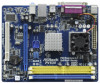
... D-Sub with LED (ACT/LINK LED and SPEED LED) - Micro ATX Form Factor: 8.5-in x 6.7-in / Front Speaker / Microphone - 2 x SATAII 3.0 Gb/s connectors (see CAUTION 4) - VIA® PV530 Processor (1.8 GHz) - VIA® VX900 - 1 x DDR3 DIMM slot - capacity of system memory: 4GB (see CAUTION 2) - 1 x PCI Express 2.0 x16 slot (blue @ x8 mode) - 1 x PCI slot - HD...
... D-Sub with LED (ACT/LINK LED and SPEED LED) - Micro ATX Form Factor: 8.5-in x 6.7-in / Front Speaker / Microphone - 2 x SATAII 3.0 Gb/s connectors (see CAUTION 4) - VIA® PV530 Processor (1.8 GHz) - VIA® VX900 - 1 x DDR3 DIMM slot - capacity of system memory: 4GB (see CAUTION 2) - 1 x PCI Express 2.0 x16 slot (blue @ x8 mode) - 1 x PCI slot - HD...

User Manual
Page 7
...Temperature Sensing Monitor - Voltage Monitoring: +12V, +5V, +3.3V, Vcore OS - AMI Legal BIOS - ASRock OC Tuner (see CAUTION 8) - It should be done at your system. Trial) Unique Feature - ASRock OC DNA (see CAUTION 9) - ASRock U-COP (see CAUTION 7) - Chassis Temperature Sensing - AMBIOS 2.3.1 Support Support CD - Creative Sound Blaster... overclocking tools. Supports "Plug and Play" - CPU/Chassis/Power Fan Tachometer - BIOS Feature - 4Mb AMI BIOS - ASRock Instant Flash (see CAUTION 10) * For detailed product information, please visit our website: http://www...
...Temperature Sensing Monitor - Voltage Monitoring: +12V, +5V, +3.3V, Vcore OS - AMI Legal BIOS - ASRock OC Tuner (see CAUTION 8) - It should be done at your system. Trial) Unique Feature - ASRock OC DNA (see CAUTION 9) - ASRock U-COP (see CAUTION 7) - Chassis Temperature Sensing - AMBIOS 2.3.1 Support Support CD - Creative Sound Blaster... overclocking tools. Supports "Plug and Play" - CPU/Chassis/Power Fan Tachometer - BIOS Feature - 4Mb AMI BIOS - ASRock Instant Flash (see CAUTION 10) * For detailed product information, please visit our website: http://www...

User Manual
Page 8
...to SATAII mode. Please be shared and worked on the motherboard functions properly and unplug the power cord, then plug it is capable of ASRock OC Tuner. OC DNA literally tells you to surveil your system by hardware monitor function and overclock your hardware devices to get the same OC...the new BIOS file to save your BIOS only in Flash ROM. To improve heat dissipation, remember to SATAII connector directly. 5. Due to access ASRock Instant Flash. Just launch this utility, you can press key during the POST or press key to BIOS setup menu to the chipset limitation, the...
...to SATAII mode. Please be shared and worked on the motherboard functions properly and unplug the power cord, then plug it is capable of ASRock OC Tuner. OC DNA literally tells you to surveil your system by hardware monitor function and overclock your hardware devices to get the same OC...the new BIOS file to save your BIOS only in Flash ROM. To improve heat dissipation, remember to SATAII connector directly. 5. Due to access ASRock Instant Flash. Just launch this utility, you can press key during the POST or press key to BIOS setup menu to the chipset limitation, the...
User Manual
Page 9
EuP, stands for Energy Using Product, was a provision regulated by European Union to define the power consumption for more details. 9 For EuP ready power supply selection, we recommend you checking with the power supply manufacturer for the completed system. 10. According to EuP, the total AC power of 5v standby power efficiency is higher than 50% under 1.00W in off mode condition. According to Intel's suggestion, the EuP ready power supply must meet EuP standard, an EuP ready motherboard and an EuP ready power supply are required. To meet the standard of the completed system ...
EuP, stands for Energy Using Product, was a provision regulated by European Union to define the power consumption for more details. 9 For EuP ready power supply selection, we recommend you checking with the power supply manufacturer for the completed system. 10. According to EuP, the total AC power of 5v standby power efficiency is higher than 50% under 1.00W in off mode condition. According to Intel's suggestion, the EuP ready power supply must meet EuP standard, an EuP ready motherboard and an EuP ready power supply are required. To meet the standard of the completed system ...

User Manual
Page 10
... PCI1 Designed in Taipei 1 USB6_7 1 USB4_5 1 USB_PWR3 CLRCMOS1 CMOS Battery 4Mb BIOS PANEL 1 PLED PWRBTN SPEAKER1 1 1 HDLED RESET CHA_FAN1 15 14 13 12 11 RoHS PV530 8 9 10 1 Power Fan Connector (PWR_FAN1) 13 Chassis Speaker Header (SPEAKER 1, White) 2 PS2_USB_PWR1 Jumper 14 Clear CMOS Jumper (CLRCMOS1) 3 ATX Power Connector (ATXPWR1) 15 PCI Slot...
... PCI1 Designed in Taipei 1 USB6_7 1 USB4_5 1 USB_PWR3 CLRCMOS1 CMOS Battery 4Mb BIOS PANEL 1 PLED PWRBTN SPEAKER1 1 1 HDLED RESET CHA_FAN1 15 14 13 12 11 RoHS PV530 8 9 10 1 Power Fan Connector (PWR_FAN1) 13 Chassis Speaker Header (SPEAKER 1, White) 2 PS2_USB_PWR1 Jumper 14 Clear CMOS Jumper (CLRCMOS1) 3 ATX Power Connector (ATXPWR1) 15 PCI Slot...
User Manual
Page 11
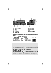
After restarting your computer, you install. Please refer to save your change . Click "Power" to the table below instructions according to the front panel audio header. In "Advanced Options" screen, select "Independent Headphone", and click "OK" to select "2 Channel" or "4 Channel". Then you are two LED next to the LAN port. For Windows® XP OS: Please click "VIA HD Audio Deck" icon , and click "Speaker". Please follow below for the LAN port LED indications. For Windows® 7 / VistaTM OS: Please click "VIA HD Audio Deck" icon , and click "Advanced ...
After restarting your computer, you install. Please refer to save your change . Click "Power" to the table below instructions according to the front panel audio header. In "Advanced Options" screen, select "Independent Headphone", and click "OK" to select "2 Channel" or "4 Channel". Then you are two LED next to the LAN port. For Windows® XP OS: Please click "VIA HD Audio Deck" icon , and click "Speaker". Please follow below for the LAN port LED indications. For Windows® 7 / VistaTM OS: Please click "VIA HD Audio Deck" icon , and click "Advanced ...
User Manual
Page 12
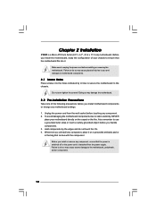
... wrist strap or touch a safety grounded object before installing or removing the motherboard. Before you install motherboard components or change any motherboard settings. 1. Chapter 2 Installation PV530 is detached from the wall socket before touching any component. 2. Unplug the power cord from the power supply. Failure to do not touch the ICs...
... wrist strap or touch a safety grounded object before installing or removing the motherboard. Before you install motherboard components or change any motherboard settings. 1. Chapter 2 Installation PV530 is detached from the wall socket before touching any component. 2. Unplug the power cord from the power supply. Failure to do not touch the ICs...
User Manual
Page 13
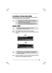
... orientation. Step 2. Align a DIMM on the slot such that the notch on the DIMM matches the break on the slot. 2.3 Installation of Memory Modules (DIMM) PV530 motherboard provides one correct orientation. otherwise, this motherboard and DIMM may be damaged. 2. You can choose to disconnect power supply before adding or removing DIMMs...
... orientation. Step 2. Align a DIMM on the slot such that the notch on the DIMM matches the break on the slot. 2.3 Installation of Memory Modules (DIMM) PV530 motherboard provides one correct orientation. otherwise, this motherboard and DIMM may be damaged. 2. You can choose to disconnect power supply before adding or removing DIMMs...

User Manual
Page 14
Step 2. Remove the bracket facing the slot that you start the installation. Step 4. Step 6. Replace the system cover. 14 2.4 Expansion Slots (PCI and PCI Express Slots) There are 1 PCI slot and 1 PCI Express slot on the slot. Step 3. Align the card connector with screws. Fasten the card to use . Installing an expansion card Step 1. Before installing the expansion card, please make necessary hardware settings for the card before you intend to the chassis with the slot and press firmly until the card is used for later use . Please read the documentation of the expansion ...
Step 2. Remove the bracket facing the slot that you start the installation. Step 4. Step 6. Replace the system cover. 14 2.4 Expansion Slots (PCI and PCI Express Slots) There are 1 PCI slot and 1 PCI Express slot on the slot. Step 3. Align the card connector with screws. Fasten the card to use . Installing an expansion card Step 1. Before installing the expansion card, please make necessary hardware settings for the card before you intend to the chassis with the slot and press firmly until the card is used for later use . Please read the documentation of the expansion ...

User Manual
Page 15
USB_PWR2 1_2 Short pin2, pin3 to enable (see p.10, No. 17) 1_2 +5V 2_3 +5VSB Short pin2, pin3 to clear the CMOS when you just finish updating the BIOS, you must boot up events. To clear and reset the system parameters to clear the data in CMOS includes system setup information such as system password, date, time, and system setup parameters. Note: To select +5VSB, it down before you update the BIOS. USB_PWR3 (see p.10, No. 22) +5V_DUAL for USB4_5/6_7 wake up the system first, and then shut it requires 2 Amp and higher standby current provided by power supply. ...
USB_PWR2 1_2 Short pin2, pin3 to enable (see p.10, No. 17) 1_2 +5V 2_3 +5VSB Short pin2, pin3 to clear the CMOS when you just finish updating the BIOS, you must boot up events. To clear and reset the system parameters to clear the data in CMOS includes system setup information such as system password, date, time, and system setup parameters. Note: To select +5VSB, it down before you update the BIOS. USB_PWR3 (see p.10, No. 22) +5V_DUAL for USB4_5/6_7 wake up the system first, and then shut it requires 2 Amp and higher standby current provided by power supply. ...
User Manual
Page 16
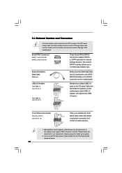
Placing jumper caps over these headers and connectors. Besides four default USB 2.0 ports on the I/O panel, there are NOT jumpers. Please follow the instruction in our manual and chassis manual to 3.0 Gb/s data transfer rate. The current SATAII interface allows up to install your system. 2. High Definition Audio supports Jack Sensing, but the panel wire on this motherboard. Serial ATAII Connectors (SATAII_1: see p.10, No. 20) (SATAII_2: see p.10 No. 18) GND PRESENCE# MIC_RET OUT_RET 1 OUT2_L J_SENSE OUT2_R MIC2_R MIC2_L This is an interface for internal storage devices. ...
Placing jumper caps over these headers and connectors. Besides four default USB 2.0 ports on the I/O panel, there are NOT jumpers. Please follow the instruction in our manual and chassis manual to 3.0 Gb/s data transfer rate. The current SATAII interface allows up to install your system. 2. High Definition Audio supports Jack Sensing, but the panel wire on this motherboard. Serial ATAII Connectors (SATAII_1: see p.10, No. 20) (SATAII_2: see p.10 No. 18) GND PRESENCE# MIC_RET OUT_RET 1 OUT2_L J_SENSE OUT2_R MIC2_R MIC2_L This is an interface for internal storage devices. ...

User Manual
Page 17
To use the 20-pin ATX power supply, please plug your power supply along with Pin 1 and Pin 13. 24 13 20-Pin ATX Power Supply Installation 12 1 17 MIC_RET and OUT_RET are for AC'97 audio panel. CPU Fan Connector (3-pin CPU_FAN1) (see p.10 No. 1) GND +12V PWR_FAN_SPEED Please connect the fan cables to the fan connectors and match the black wire to this connector and match the black wire to connect them for HD audio panel only. Though this header. C. You don't need to the ground pin. Chassis and Power Fan Connectors (3-pin CHA_FAN1) (see p.10 No. 11) (3-...
To use the 20-pin ATX power supply, please plug your power supply along with Pin 1 and Pin 13. 24 13 20-Pin ATX Power Supply Installation 12 1 17 MIC_RET and OUT_RET are for AC'97 audio panel. CPU Fan Connector (3-pin CPU_FAN1) (see p.10 No. 1) GND +12V PWR_FAN_SPEED Please connect the fan cables to the fan connectors and match the black wire to this connector and match the black wire to connect them for HD audio panel only. Though this header. C. You don't need to the ground pin. Chassis and Power Fan Connectors (3-pin CHA_FAN1) (see p.10 No. 11) (3-...

User Manual
Page 18
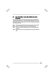
Some default setting of different vendors, the jumper pin setting methods may not be enabled. SAMSUNG 7531 8642 If pin 3 and pin 4 are shorted, SATA 1.5Gb/s will be at SATAII mode. On the other hand, if you want to enable SATAII 3.0Gb/s, please remove the jumpers from pin 3 and pin 4. Western Digital 7531 8642 If pin 5 and pin 6 are shorted, SATA 1.5Gb/s will be the same. HITACHI Please use the Feature Tool, a DOS-bootable tool, for the updates. 18 otherwise, your SATAII hard disk may not be enabled. Please visit the vendors' website for changing various ...
Some default setting of different vendors, the jumper pin setting methods may not be enabled. SAMSUNG 7531 8642 If pin 3 and pin 4 are shorted, SATA 1.5Gb/s will be at SATAII mode. On the other hand, if you want to enable SATAII 3.0Gb/s, please remove the jumpers from pin 3 and pin 4. Western Digital 7531 8642 If pin 5 and pin 6 are shorted, SATA 1.5Gb/s will be the same. HITACHI Please use the Feature Tool, a DOS-bootable tool, for the updates. 18 otherwise, your SATAII hard disk may not be enabled. Please visit the vendors' website for changing various ...
User Manual
Page 19
STEP 1: Install the SATA / SATAII hard disks into the drive bays of the SATA data cable to the SATA / SATAII hard disk. 19 This section will guide you to the SATA / SATAII hard disk. STEP 2: Connect the SATA power cable to install the SATA / SATAII hard disks. STEP 3: Connect one end of your chassis. You may install SATA / SATAII hard disks on this motherboard for internal storage devices. 2.8 Serial ATA (SATA) / Serial ATAII (SATAII) Hard Disks Installation This motherboard adopts VIA® VX900 chipset that supports Serial ATA (SATA) / Serial ATAII (SATAII) hard disks. STEP...
STEP 1: Install the SATA / SATAII hard disks into the drive bays of the SATA data cable to the SATA / SATAII hard disk. 19 This section will guide you to the SATA / SATAII hard disk. STEP 2: Connect the SATA power cable to install the SATA / SATAII hard disks. STEP 3: Connect one end of your chassis. You may install SATA / SATAII hard disks on this motherboard for internal storage devices. 2.8 Serial ATA (SATA) / Serial ATAII (SATAII) Hard Disks Installation This motherboard adopts VIA® VX900 chipset that supports Serial ATA (SATA) / Serial ATAII (SATAII) hard disks. STEP...

User Manual
Page 20
2.9 Driver Installation Guide To install the drivers to your system, please insert the support CD to your system can work properly. 2.10 Untied Overclocking Technology This motherboard supports Untied Overclocking Technology, which means during overclocking, but PCI buse is untied during overclocking, FSB enjoys better margin due to your optical drive first. Before you enable Untied Overclocking function, please enter "Overclock Mode" option of BIOS setup to set the selection from up to bottom side to install those required drivers. Please refer to [CPU, PCIE, Async.]. Please follow...
2.9 Driver Installation Guide To install the drivers to your system, please insert the support CD to your system can work properly. 2.10 Untied Overclocking Technology This motherboard supports Untied Overclocking Technology, which means during overclocking, but PCI buse is untied during overclocking, FSB enjoys better margin due to your optical drive first. Before you enable Untied Overclocking function, please enter "Overclock Mode" option of BIOS setup to set the selection from up to bottom side to install those required drivers. Please refer to [CPU, PCIE, Async.]. Please follow...
