
User Manual
Page 4
3.4.4 ACPI Configuration 45 3.4.5 IDE Configuration 46 3.4.6 PCIPnP Configuration 48 3.4.7 Floppy Configuration 49 3.4.8 Super IO Configuration 49 3.4.9 USB Configuration 50 3.5 Hardware Health Event Monitoring Screen 51 3.6 Boot Screen 52 3.6.1 Boot Settings Configuration 52 3.7 Security Screen 53 3.8 Exit Screen 54 4 Software Support 55 4.1 Install Operating System 55 4.2 Support CD Information 55 4.2.1 Running Support CD 55 4.2.2 Drivers Menu 55 4.2.3 Utilities Menu 55 4.2.4 Contact Information 55 4
3.4.4 ACPI Configuration 45 3.4.5 IDE Configuration 46 3.4.6 PCIPnP Configuration 48 3.4.7 Floppy Configuration 49 3.4.8 Super IO Configuration 49 3.4.9 USB Configuration 50 3.5 Hardware Health Event Monitoring Screen 51 3.6 Boot Screen 52 3.6.1 Boot Settings Configuration 52 3.7 Security Screen 53 3.8 Exit Screen 54 4 Software Support 55 4.1 Install Operating System 55 4.2 Support CD Information 55 4.2.1 Running Support CD 55 4.2.2 Drivers Menu 55 4.2.3 Utilities Menu 55 4.2.4 Contact Information 55 4

User Manual
Page 5
... (ATX Form Factor: 12.0-in x 8.5-in, 30.5 cm x 21.6 cm) ASRock P43DE Quick Installation Guide ASRock P43DE Support CD One 80-conductor Ultra ATA 66/100/133 IDE Ribbon Cable Two Serial ATA (SATA) Data Cables (Optional) One Serial..., please visit our website for specific information about the model you for purchasing ASRock P43DE motherboard, a reliable motherboard produced under ASRock's consistently stringent quality control. You may find the latest VGA cards and CPU support lists on ASRock website without notice. It delivers excellent performance with robust design conforming to...
... (ATX Form Factor: 12.0-in x 8.5-in, 30.5 cm x 21.6 cm) ASRock P43DE Quick Installation Guide ASRock P43DE Support CD One 80-conductor Ultra ATA 66/100/133 IDE Ribbon Cable Two Serial ATA (SATA) Data Cables (Optional) One Serial..., please visit our website for specific information about the model you for purchasing ASRock P43DE motherboard, a reliable motherboard produced under ASRock's consistently stringent quality control. You may find the latest VGA cards and CPU support lists on ASRock website without notice. It delivers excellent performance with robust design conforming to...

User Manual
Page 6
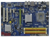
...see CAUTION 3) - 4 x DDR2 DIMM slots - PCIE x1 Gigabit LAN 10/100/1000 Mb/s - capacity of system memory: 16GB (see CAUTION 7) - 1 x ATA133 IDE connector (supports 2 x IDE devices) - 1 x Floppy connector - 1 x IR header - 1 x COM port header 6 LGA 775 for Intel® CoreTM 2 Extreme / CoreTM 2 Quad .../ CoreTM 2 Duo / Pentium® Dual Core / Celeron® Dual Core / Celeron®, supporting Penryn Quad Core Yorkfield and Dual Core Wolfdale processors - HD Audio Jack: Side Speaker/Rear Speaker/Central/Bass/ Line in , 30.5 cm x 21.6 ...
...see CAUTION 3) - 4 x DDR2 DIMM slots - PCIE x1 Gigabit LAN 10/100/1000 Mb/s - capacity of system memory: 16GB (see CAUTION 7) - 1 x ATA133 IDE connector (supports 2 x IDE devices) - 1 x Floppy connector - 1 x IR header - 1 x COM port header 6 LGA 775 for Intel® CoreTM 2 Extreme / CoreTM 2 Quad .../ CoreTM 2 Duo / Pentium® Dual Core / Celeron® Dual Core / Celeron®, supporting Penryn Quad Core Yorkfield and Dual Core Wolfdale processors - HD Audio Jack: Side Speaker/Rear Speaker/Central/Bass/ Line in , 30.5 cm x 21.6 ...

User Manual
Page 7
... CAUTION 8) - 1 x USB/WiFi header (see CAUTION 10) - O. Chassis Fan Tachometer - Intelligent Energy Saver (see CAUTION 13) - CPU Temperature Sensing Monitor - Chassis Temperature Sensing - Supports Jumperfree - Hybrid Booster: - ASRock U-COP (see CAUTION 11) - Microsoft® Windows® 2000 / XP / XP 64-bit / VistaTM / VistaTM 64-bit compliant (see CAUTION 12) - CD in header...
... CAUTION 8) - 1 x USB/WiFi header (see CAUTION 10) - O. Chassis Fan Tachometer - Intelligent Energy Saver (see CAUTION 13) - CPU Temperature Sensing Monitor - Chassis Temperature Sensing - Supports Jumperfree - Hybrid Booster: - ASRock U-COP (see CAUTION 11) - Microsoft® Windows® 2000 / XP / XP 64-bit / VistaTM / VistaTM 64-bit compliant (see CAUTION 12) - CD in header...

User Manual
Page 8
... and expense. It allows you implement Dual Channel Memory Technology, make sure to support 2 USB 2.0 ports. Due to the components and devices of your system. You can also be used to support WiFi+AP function with ASRock WiFi-802.11g or WiFi- 802.11n module, an easy-to create a...read the "SATAII Hard Disk Setup Guide" on page 33 for the CPU FSB frequency and its corresponding memory support frequency. channel, 6-channel, and 8-channel modes. About the setting of ASRock WiFi-802.11g or WiFi-802.11n module. Overclocking may affect your system stability, or even cause damage ...
... and expense. It allows you implement Dual Channel Memory Technology, make sure to support 2 USB 2.0 ports. Due to the components and devices of your system. You can also be used to support WiFi+AP function with ASRock WiFi-802.11g or WiFi- 802.11n module, an easy-to create a...read the "SATAII Hard Disk Setup Guide" on page 33 for the CPU FSB frequency and its corresponding memory support frequency. channel, 6-channel, and 8-channel modes. About the setting of ASRock WiFi-802.11g or WiFi-802.11n module. Overclocking may affect your system stability, or even cause damage ...
User Manual
Page 9
...overclock your hardware devices to use IDE mode under Windows® 2000 OS. Please refer to perform over-clocking. ASRock website: http://www.asrock.com 12. AHCI function is able to spray thermal grease between the CPU and the heatsink when you install the ...software design, Intelligent Energy Saver is detected, the system will automatically shutdown. Although this motherboard offers stepless control, it is not supported under Windows® 2000. To improve heat dissipation, remember to provide exceptional power saving and improve power efficiency without sacrificing computing ...
...overclock your hardware devices to use IDE mode under Windows® 2000 OS. Please refer to perform over-clocking. ASRock website: http://www.asrock.com 12. AHCI function is able to spray thermal grease between the CPU and the heatsink when you install the ...software design, Intelligent Energy Saver is detected, the system will automatically shutdown. Although this motherboard offers stepless control, it is not supported under Windows® 2000. To improve heat dissipation, remember to provide exceptional power saving and improve power efficiency without sacrificing computing ...
User Manual
Page 15
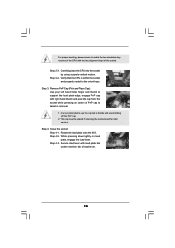
... cap. 2. Step 4. Rotate the load plate onto the IHS. Remove PnP Cap (Pick and Place Cap): Use your left hand index finger and thumb to support the load plate edge, engage PnP cap with the two alignment keys of the socket. For proper inserting, please ensure to match the two orientation...
... cap. 2. Step 4. Rotate the load plate onto the IHS. Remove PnP Cap (Pick and Place Cap): Use your left hand index finger and thumb to support the load plate edge, engage PnP cap with the two alignment keys of the socket. For proper inserting, please ensure to match the two orientation...
User Manual
Page 16
... interface material onto center of heatsink and cooling fan compliant with fan operation or contact other . Step 4. Repeat with the motherboard throughholes. Step 6. Ensure that supports Intel 775-LAND CPU. Step 3. Secure excess cable with tie-wrap to the CPU fan connector on side closest to ensure cable does not interfere...
... interface material onto center of heatsink and cooling fan compliant with fan operation or contact other . Step 4. Repeat with the motherboard throughholes. Step 6. Ensure that supports Intel 775-LAND CPU. Step 3. Secure excess cable with tie-wrap to the CPU fan connector on side closest to ensure cable does not interfere...

User Manual
Page 17
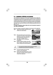
... install four DDR2 DIMMs for example, installing a pair of Memory Modules (DIMM) This motherboard provides four 240-pin DDR2 (Double Data Rate 2) DIMM slots, and supports Dual Channel Memory Technology. see p.10 No.7), so that Dual Channel Memory Technology can be damaged. 17 2.5 Installation of memory modules in all four slots...
... install four DDR2 DIMMs for example, installing a pair of Memory Modules (DIMM) This motherboard provides four 240-pin DDR2 (Double Data Rate 2) DIMM slots, and supports Dual Channel Memory Technology. see p.10 No.7), so that Dual Channel Memory Technology can be damaged. 17 2.5 Installation of memory modules in all four slots...

User Manual
Page 21
... storage devices. FDD connector (33-pin FLOPPY1) (see p.10, No. 17) SATAII_3 (Port 2) SATAII_4 (Port 3) SATAII_5 (Port 4) SATAII_6 (Port 5) These six Serial ATAII (SATAII) connectors support SATA data cables for the details. Serial ATAII Connectors (SATAII_1 (Port 0): see p.10, No. 11) SATAII_1 (Port 0) (SATAII_2 (Port 1): see p.10, No. 12) SATAII_2 (Port...
... storage devices. FDD connector (33-pin FLOPPY1) (see p.10, No. 17) SATAII_3 (Port 2) SATAII_4 (Port 3) SATAII_5 (Port 4) SATAII_6 (Port 5) These six Serial ATAII (SATAII) connectors support SATA data cables for the details. Serial ATAII Connectors (SATAII_1 (Port 0): see p.10, No. 11) SATAII_1 (Port 0) (SATAII_2 (Port 1): see p.10, No. 12) SATAII_2 (Port...

User Manual
Page 22
It can also be used to support WiFi+AP function with ASRock WiFi-802. 11g or WiFi-802.11n module, an easy-to the power connector on this motherboard. This connector allows you to the power connector ... and enjoy the convenience of SATA power cable to -use wireless local area network (WLAN) adapter. This header supports an optional wireless transmitting and receiving infrared module. Each USB 2.0 header can be used to support 2 USB 2.0 ports. P+ GND N/C +5V Infrared Module Header (5-pin IR1) (see p.10 No. 26) Internal Audio Connectors (4-pin...
It can also be used to support WiFi+AP function with ASRock WiFi-802. 11g or WiFi-802.11n module, an easy-to the power connector on this motherboard. This connector allows you to the power connector ... and enjoy the convenience of SATA power cable to -use wireless local area network (WLAN) adapter. This header supports an optional wireless transmitting and receiving infrared module. Each USB 2.0 header can be used to support 2 USB 2.0 ports. P+ GND N/C +5V Infrared Module Header (5-pin IR1) (see p.10 No. 26) Internal Audio Connectors (4-pin...
User Manual
Page 23
... Connector (4-pin CPU_FAN1) (see p.10, No. 4) 1 GND Please connect a CPU fan cable 2 +12V 3 CPU_FAN_SPEED to this header. High Definition Audio supports Jack Sensing, but the panel wire on the chassis must support HDA to [Enabled]. Set the Front Panel Control option from [Auto] to function correctly. Chassis Speaker Header (4-pin SPEAKER 1) (see...
... Connector (4-pin CPU_FAN1) (see p.10, No. 4) 1 GND Please connect a CPU fan cable 2 +12V 3 CPU_FAN_SPEED to this header. High Definition Audio supports Jack Sensing, but the panel wire on the chassis must support HDA to [Enabled]. Set the Front Panel Control option from [Auto] to function correctly. Chassis Speaker Header (4-pin SPEAKER 1) (see...
User Manual
Page 24
... 3-Pin Fan Installation ATX Power Connector (24-pin ATXPWR1) (see p.10 No. 24) RRXD1 DDTR#1 DDSR#1 CCTS#1 1 RRI#1 RRTS#1 GND TTXD1 DDCD#1 This COM1 header supports a serial port module. 24 Though this motherboard, please connect it can still work successfully even without the fan speed control function. If you plan to... Header (9-pin COM1) (see p.10 No. 8) 12 24 Please connect an ATX power supply to Pin 1-3. Though this motherboard provides 4-Pin CPU fan (Quiet Fan) support, the 3-Pin CPU fan still can work if you adopt a traditional 4-pin ATX 5 1 12V power supply.
... 3-Pin Fan Installation ATX Power Connector (24-pin ATXPWR1) (see p.10 No. 24) RRXD1 DDTR#1 DDSR#1 CCTS#1 1 RRI#1 RRTS#1 GND TTXD1 DDCD#1 This COM1 header supports a serial port module. 24 Though this motherboard, please connect it can still work successfully even without the fan speed control function. If you plan to... Header (9-pin COM1) (see p.10 No. 8) 12 24 Please connect an ATX power supply to Pin 1-3. Though this motherboard provides 4-Pin CPU fan (Quiet Fan) support, the 3-Pin CPU fan still can work if you adopt a traditional 4-pin ATX 5 1 12V power supply.

User Manual
Page 27
... follow the below SATAII hard disk setup guide. Western Digital 7531 8642 If pin 5 and pin 6 are just for details: http://www.hitachigst.com/hdd/support/download.htm The above examples are shorted, SATA 1.5Gb/s will be the same. For different SATAII hard disk products of SATAII hard disks may not...
... follow the below SATAII hard disk setup guide. Western Digital 7531 8642 If pin 5 and pin 6 are just for details: http://www.hitachigst.com/hdd/support/download.htm The above examples are shorted, SATA 1.5Gb/s will be the same. For different SATAII hard disk products of SATAII hard disks may not...

User Manual
Page 28
...SATA / SATAII hard disks. This section will guide you to the motherboard's SATAII connector. Intel® ICH10 south bridge chipset provides hardware support for Advanced Host controller Interface (AHCI), a new programming interface for internal storage devices. It is not recommended to insert and remove the ...for the action to switch the "Configure SATAII as" setting after OS installation. 2.12 Hot Plug Function for SATA / SATAII HDDs P43DE supports Hot Plug function for RAID configuration, it cannot perform Hot Plug if the OS has been installed into the drive bays of the ...
...SATA / SATAII hard disks. This section will guide you to the motherboard's SATAII connector. Intel® ICH10 south bridge chipset provides hardware support for Advanced Host controller Interface (AHCI), a new programming interface for internal storage devices. It is not recommended to insert and remove the ...for the action to switch the "Configure SATAII as" setting after OS installation. 2.12 Hot Plug Function for SATA / SATAII HDDs P43DE supports Hot Plug function for RAID configuration, it cannot perform Hot Plug if the OS has been installed into the drive bays of the ...

User Manual
Page 29
... the risk of HDD crash or data loss. 29 Below operation procedure is designed only for SATA / SATAII HDD in the product spec on our support website: www.asrock.com 4. Please follow below instructions step by the chipset because of its limitation, the SATA / SATAII Hot Plug...
... the risk of HDD crash or data loss. 29 Below operation procedure is designed only for SATA / SATAII HDD in the product spec on our support website: www.asrock.com 4. Please follow below instructions step by the chipset because of its limitation, the SATA / SATAII Hot Plug...
User Manual
Page 31
... The system will start to generate Serial ATA driver diskette [YN]?", press . Therefore, the drivers you install can be auto-detected and listed on the support CD driver page. STEP 2: Make a SATA / SATAII driver diskette. D. Please insert a floppy diskette into the floppy diskette. 31 Set "SATAII Configuration...follow below procedures according to [AHCI]. Since Windows® 2000 AHCI driver is not provided by the chipset vendor, AHCI function is not supported under Windows® 2000. 2.15.1 Installing Windows® 2000 / XP / XP 64-bit Without RAID Functions If you want to ...
... The system will start to generate Serial ATA driver diskette [YN]?", press . Therefore, the drivers you install can be auto-detected and listed on the support CD driver page. STEP 2: Make a SATA / SATAII driver diskette. D. Please insert a floppy diskette into the floppy diskette. 31 Set "SATAII Configuration...follow below procedures according to [AHCI]. Since Windows® 2000 AHCI driver is not provided by the chipset vendor, AHCI function is not supported under Windows® 2000. 2.15.1 Installing Windows® 2000 / XP / XP 64-bit Without RAID Functions If you want to ...

User Manual
Page 32
.... STEP 2: Install Windows® VistaTM / VistaTM 64-bit OS on the bottom to load the Intel® AHCI drivers. page, please insert the ASRock Support CD into your optical drive, and click the "Load Driver" button on the left on your system. STEP 3: Install Windows® XP / XP ...system, and follow below steps. Using SATA / SATAII HDDs with NCQ function STEP 1: Set Up BIOS. B. Set "SATAII Configuration" to [Enhanced], and then in our Support CD: .. \ I386 (For Windows® VistaTM OS) .. \ AMD64 (For Windows® VistaTM 64-bit OS) After that, please insert Windows® VistaTM /...
.... STEP 2: Install Windows® VistaTM / VistaTM 64-bit OS on the bottom to load the Intel® AHCI drivers. page, please insert the ASRock Support CD into your optical drive, and click the "Load Driver" button on the left on your system. STEP 3: Install Windows® XP / XP ...system, and follow below steps. Using SATA / SATAII HDDs with NCQ function STEP 1: Set Up BIOS. B. Set "SATAII Configuration" to [Enhanced], and then in our Support CD: .. \ I386 (For Windows® VistaTM OS) .. \ AMD64 (For Windows® VistaTM 64-bit OS) After that, please insert Windows® VistaTM /...

User Manual
Page 33
... Mode" option of BIOS setup to set the option to [Manual]. Please refer to the warning on your system. 2.16 Untied Overclocking Technology This motherboard supports Untied Overclocking Technology, which means during overclocking, but PCI / PCIE buses are in the option "Configure SATAII as", please set the selection from [Auto] to...
... Mode" option of BIOS setup to set the option to [Manual]. Please refer to the warning on your system. 2.16 Untied Overclocking Technology This motherboard supports Untied Overclocking Technology, which means during overclocking, but PCI / PCIE buses are in the option "Configure SATAII as", please set the selection from [Auto] to...
User Manual
Page 38
... Configuration options: [Auto], [Enabled] and [Disabled]. Please note that enabling this motherboard. This item will be hidden if the current CPU does not support Intel (R) SpeedStep(tm) tech.. Therefore, you are allowed to adjust the CPU frequency and PCIE frequency in the following two items. If you select [I...to adjust PCIE frequency. Intel (R) SpeedStep(tm) tech. Please refer to page 33 for the CPU FSB frequency and its corresponding memory support frequency. 38 Ratio CMOS Setting If the ratio status is unlocked, you will find this item appear to allow you changing the ratio ...
... Configuration options: [Auto], [Enabled] and [Disabled]. Please note that enabling this motherboard. This item will be hidden if the current CPU does not support Intel (R) SpeedStep(tm) tech.. Therefore, you are allowed to adjust the CPU frequency and PCIE frequency in the following two items. If you select [I...to adjust PCIE frequency. Intel (R) SpeedStep(tm) tech. Please refer to page 33 for the CPU FSB frequency and its corresponding memory support frequency. 38 Ratio CMOS Setting If the ratio status is unlocked, you will find this item appear to allow you changing the ratio ...


