
User Manual
Page 4
3.4.4 Storage Configuration 47 3.4.5 PCIPnP Configuration 49 3.4.6 Floppy Configuration 50 3.4.7 Super IO Configuration 50 3.4.8 USB Configuration 52 3.5 Hardware Health Event Monitoring Screen 53 3.6 Boot Screen 54 3.6.1 Boot Settings Configuration 54 3.7 Security Screen 55 3.8 Exit Screen 56 4 . Software Support 57 4.1 Install Operating System 57 4.2 Support CD Information 57 4.2.1 Running Support CD 57 4.2.2 Drivers Menu 57 4.2.3 Utilities Menu 57 4.2.4 Contact Information 57 4
3.4.4 Storage Configuration 47 3.4.5 PCIPnP Configuration 49 3.4.6 Floppy Configuration 50 3.4.7 Super IO Configuration 50 3.4.8 USB Configuration 52 3.5 Hardware Health Event Monitoring Screen 53 3.6 Boot Screen 54 3.6.1 Boot Settings Configuration 54 3.7 Security Screen 55 3.8 Exit Screen 56 4 . Software Support 57 4.1 Install Operating System 57 4.2 Support CD Information 57 4.2.1 Running Support CD 57 4.2.2 Drivers Menu 57 4.2.3 Utilities Menu 57 4.2.4 Contact Information 57 4

User Manual
Page 7
...Frequency Stepless Control (see CAUTION 12) - Boot Failure Guard (B.F.G.) - CPU/Chassis/Power FAN connector - 24 pin ATX power connector - 4 pin 12V power connector - Drivers, Utilities, AntiVirus Software (Trial Version), ASRock Software Suite (CyberLink DVD Suite and Creative Sound... Blaster X-Fi MB) (OEM and Trial Version) - Intelligent Energy Saver (see CAUTION 15) - Instant Boot - Front panel audio header - 3 x USB 2.0 headers (...
...Frequency Stepless Control (see CAUTION 12) - Boot Failure Guard (B.F.G.) - CPU/Chassis/Power FAN connector - 24 pin ATX power connector - 4 pin 12V power connector - Drivers, Utilities, AntiVirus Software (Trial Version), ASRock Software Suite (CyberLink DVD Suite and Creative Sound... Blaster X-Fi MB) (OEM and Trial Version) - Intelligent Energy Saver (see CAUTION 15) - Instant Boot - Front panel audio header - 3 x USB 2.0 headers (...

User Manual
Page 19
... "Identify" button to be Primary, and all additional monitors will disable onboard VGA/D-Sub function when the add-on the I/O panel of Multi Monitor feature. Boot your primary monitor, and then select "Primary". Right-click the display icon in the Display Properties dialog that you can adjust the parameters of the...
... "Identify" button to be Primary, and all additional monitors will disable onboard VGA/D-Sub function when the add-on the I/O panel of Multi Monitor feature. Boot your primary monitor, and then select "Primary". Right-click the display icon in the Display Properties dialog that you can adjust the parameters of the...

User Manual
Page 20
...: CLRCMOS1 allows you need to positions representing the physical setup of display icons determines how you do not clear the CMOS right after you must boot up events. The data in CMOS. If you to short pin2 and pin3 on these 2 pins. Click and drag the display icons to clear the...
...: CLRCMOS1 allows you need to positions representing the physical setup of display icons determines how you do not clear the CMOS right after you must boot up events. The data in CMOS. If you to short pin2 and pin3 on these 2 pins. Click and drag the display icons to clear the...
User Manual
Page 29
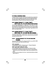
.../ XP / XP 64-bit on your SATA / SATAII HDDs with RAID functions, please follow below steps. B. Please select CD-ROM as the boot device. STEP 1: Set Up BIOS. C. Enter BIOS SETUP UTILITY Advanced screen Storage Configuration. Set the "SATA Operation Mode" option to install those ...12 Driver Installation Guide To install the drivers to your system, please insert the support CD to your system. A. Insert the ASRock Support CD into your optical drive to boot your optical drive first. Then, the drivers compatible to your system can work properly. 2.13 Installing Windows® 7 / ...
.../ XP / XP 64-bit on your SATA / SATAII HDDs with RAID functions, please follow below steps. B. Please select CD-ROM as the boot device. STEP 1: Set Up BIOS. C. Enter BIOS SETUP UTILITY Advanced screen Storage Configuration. Set the "SATA Operation Mode" option to install those ...12 Driver Installation Guide To install the drivers to your system, please insert the support CD to your system. A. Insert the ASRock Support CD into your optical drive to boot your optical drive first. Then, the drivers compatible to your system can work properly. 2.13 Installing Windows® 7 / ...

User Manual
Page 31
page, please insert the ASRock Support CD into the optical drive to boot your system, and follow the instruction to install Windows® 7 / 7 .... NOTE. Please use the native driver to install Windows® 7 / 7 64-bit OS, and then install ASRock All-in the fixed mode so that , please insert Windows® VistaTM / VistaTM 64-bit optical disk into the...VistaTM 64-bit optical disk into your system. When you see "Where do not need to set the selection from ASRock support CD. Before you enable Untied Overclocking function, please enter "Overclock Mode" option of BIOS setup to set up ...
page, please insert the ASRock Support CD into the optical drive to boot your system, and follow the instruction to install Windows® 7 / 7 .... NOTE. Please use the native driver to install Windows® 7 / 7 64-bit OS, and then install ASRock All-in the fixed mode so that , please insert Windows® VistaTM / VistaTM 64-bit optical disk into the...VistaTM 64-bit optical disk into your system. When you see "Where do not need to set the selection from ASRock support CD. Before you enable Untied Overclocking function, please enter "Overclock Mode" option of BIOS setup to set up ...
User Manual
Page 32
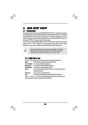
... system time/date information OC Tweaker To set up overclocking features Advanced To set up the advanced BIOS features H/W Monitor To display current hardware status Boot To set up the default system device to configure your screen. 3.1.1 BIOS Menu Bar The top of the screen has a menu bar with its test...
... system time/date information OC Tweaker To set up overclocking features Advanced To set up the advanced BIOS features H/W Monitor To display current hardware status Boot To set up the default system device to configure your screen. 3.1.1 BIOS Menu Bar The top of the screen has a menu bar with its test...

User Manual
Page 33
... 3.2 Main Screen When you enter the BIOS SETUP UTILITY, the Main screen will appear and display the system overview. N68C-GS UCC BIOS SETUP UTILITY Main OC Tweaker Advanced H/W Monitor Boot Security Exit System Overview System Time System Date [17:00:09] [Fri 02/12/2010] BIOS Version... : N68C-GS UCC P1.00 Processor Type : AMD Athlon (tm) 64 X2 Dual Core Processor 4000+ (64bit) Processor Speed : 2000MHz Microcode Update : 40F32/62...
... 3.2 Main Screen When you enter the BIOS SETUP UTILITY, the Main screen will appear and display the system overview. N68C-GS UCC BIOS SETUP UTILITY Main OC Tweaker Advanced H/W Monitor Boot Security Exit System Overview System Time System Date [17:00:09] [Fri 02/12/2010] BIOS Version... : N68C-GS UCC P1.00 Processor Type : AMD Athlon (tm) 64 X2 Dual Core Processor 4000+ (64bit) Processor Speed : 2000MHz Microcode Update : 40F32/62...

User Manual
Page 34
Use [+] or [-] to select a field. N68C-S UCC BIOS SETUP UTILITY Main OC Tweaker Advanced H/W Monitor Boot Security Exit System Overview System Time System Date [17:00:09] [Fri 02/12/2010] BIOS Version : N68C-S UCC P1.00 Processor Type : AMD Athlon (tm) 64 X2 Dual Core Processor 4000+ (64bit) Processor Speed : 2000MHz Microcode Update : 40F32/62...
Use [+] or [-] to select a field. N68C-S UCC BIOS SETUP UTILITY Main OC Tweaker Advanced H/W Monitor Boot Security Exit System Overview System Time System Date [17:00:09] [Fri 02/12/2010] BIOS Version : N68C-S UCC P1.00 Processor Type : AMD Athlon (tm) 64 X2 Dual Core Processor 4000+ (64bit) Processor Speed : 2000MHz Microcode Update : 40F32/62...

User Manual
Page 35
...3.3 OC Tweaker Screen In the OC Tweaker screen, you can use this option to adjust CPU frequency. BIOS SETUP UTILITY Main OC Tweaker Advanced H/W Monitor Boot Security Exit EZ Overclocking Load Optimized CPU OC Setting CPU Configuration Overclock Mode CPU Frequency (MHz) PCIE Frequency (MHz...) Boot Failure Guard CPU/LDT Spread Spectrum PCIE Spread Spectrum SATA Spread Spectrum Processor Maximum Frequency Processor Maximum Voltage Multiplier/Voltage Change HT Bus Speed ...
...3.3 OC Tweaker Screen In the OC Tweaker screen, you can use this option to adjust CPU frequency. BIOS SETUP UTILITY Main OC Tweaker Advanced H/W Monitor Boot Security Exit EZ Overclocking Load Optimized CPU OC Setting CPU Configuration Overclock Mode CPU Frequency (MHz) PCIE Frequency (MHz...) Boot Failure Guard CPU/LDT Spread Spectrum PCIE Spread Spectrum SATA Spread Spectrum Processor Maximum Frequency Processor Maximum Voltage Multiplier/Voltage Change HT Bus Speed ...

User Manual
Page 36
...this item. 36 CPU Frequency Multiplier This option appears only when you adopt AM2 CPU. BIOS SETUP UTILITY Main OC Tweaker Advanced H/W Monitor Boot Security Exit EZ Overclocking Load Optimized CPU OC Setting CPU Configuration Overclock Mode CPU Frequency (MHz) PCIE Frequency (MHz...) Boot Failure Guard CPU/LDT Spread Spectrum PCIE Spread Spectrum SATA Spread Spectrum Processor Maximum Frequency Processor Maximum Voltage Multiplier/Voltage Change Processor Multiplier ...
...this item. 36 CPU Frequency Multiplier This option appears only when you adopt AM2 CPU. BIOS SETUP UTILITY Main OC Tweaker Advanced H/W Monitor Boot Security Exit EZ Overclocking Load Optimized CPU OC Setting CPU Configuration Overclock Mode CPU Frequency (MHz) PCIE Frequency (MHz...) Boot Failure Guard CPU/LDT Spread Spectrum PCIE Spread Spectrum SATA Spread Spectrum Processor Maximum Frequency Processor Maximum Voltage Multiplier/Voltage Change Processor Multiplier ...
User Manual
Page 42
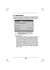
... Exit ESC Exit v02.54 (C) Copyright 1985-2005, American Megatrends, Inc. BIOS SETUP UTILITY Main OC Tweaker Advanced H/W Monitor Boot Security Exit Advanced Settings WARNING : Setting wrong values in below sections may cause the system to your USB flash drive, floppy ...for CPU CPU Configuration Chipset Configuration ACPI Configuration Storage Configuration PCIPnP Configuration Floppy Configuration SuperIO Configuration USB Configuration BIOS Update Utility ASRock Instant Flash Select Screen Select Item Enter Go to update your BIOS, and reboot your system after BIOS update process ...
... Exit ESC Exit v02.54 (C) Copyright 1985-2005, American Megatrends, Inc. BIOS SETUP UTILITY Main OC Tweaker Advanced H/W Monitor Boot Security Exit Advanced Settings WARNING : Setting wrong values in below sections may cause the system to your USB flash drive, floppy ...for CPU CPU Configuration Chipset Configuration ACPI Configuration Storage Configuration PCIPnP Configuration Floppy Configuration SuperIO Configuration USB Configuration BIOS Update Utility ASRock Instant Flash Select Screen Select Item Enter Go to update your BIOS, and reboot your system after BIOS update process ...

User Manual
Page 45
... Option General Help Load Defaults Save and Exit Exit v02.54 (C) Copyright 1985-2003, American Megatrends, Inc. If [Power Off] is [Disabled]. If you to boot up when the power recovers. Check Ready Bit Use this item to enable or disable Ring-In signals to enable or disable the feature Check...
... Option General Help Load Defaults Save and Exit Exit v02.54 (C) Copyright 1985-2003, American Megatrends, Inc. If [Power Off] is [Disabled]. If you to boot up when the power recovers. Check Ready Bit Use this item to enable or disable Ring-In signals to enable or disable the feature Check...

User Manual
Page 53
... default value is [Fast]. Target Fan Speed Use this section, it allows you install 4-pin CPU fan. BIOS SETUP UTILITY Main OC Tweaker Advanced H/W Monitor Boot Security Exit Hardware Health Event Monitoring CPU Temperature M / B Temperature CPU Fan Speed Chassis Fan Speed Power Fan Speed Vcore + 3.30V + 5.00V + 12.00V CPU Quiet...
... default value is [Fast]. Target Fan Speed Use this section, it allows you install 4-pin CPU fan. BIOS SETUP UTILITY Main OC Tweaker Advanced H/W Monitor Boot Security Exit Hardware Health Event Monitoring CPU Temperature M / B Temperature CPU Fan Speed Chassis Fan Speed Power Fan Speed Vcore + 3.30V + 5.00V + 12.00V CPU Quiet...

User Manual
Page 54
...option to enable or disable OEM Logo. The default value is [Enabled]. Configuration options: [Auto], [S-series], [Scenery] and [ASRock]. Enabled: Displays OEM Logo instead of POST messages. +F1 F9 F10 ESC Select Screen Select Item Change Option General Help Load ...AddOn ROM information when the system boots, please select [Enabled]. BIOS SETUP UTILITY Main OC Tweaker Advanced H/W Monitor Boot Security Exit Boot Settings Boot Settings Configuration Configure Settings during System Boot. 1st Boot Device 2nd Boot Device 3rd Boot Device 4th Boot Device Hard Disk Drives Removable Drives ...
...option to enable or disable OEM Logo. The default value is [Enabled]. Configuration options: [Auto], [S-series], [Scenery] and [ASRock]. Enabled: Displays OEM Logo instead of POST messages. +F1 F9 F10 ESC Select Screen Select Item Change Option General Help Load ...AddOn ROM information when the system boots, please select [Enabled]. BIOS SETUP UTILITY Main OC Tweaker Advanced H/W Monitor Boot Security Exit Boot Settings Boot Settings Configuration Configure Settings during System Boot. 1st Boot Device 2nd Boot Device 3rd Boot Device 4th Boot Device Hard Disk Drives Removable Drives ...

User Manual
Page 55
...: Not Installed User Password : Not Installed Change Supervisor Password Change User Password Install or Change the password. Boot Up Num-Lock If this section, you may set to enable or disable the Boot From Onboard LAN feature. For the user password, you may also clear it will automatically activate the Numeric... Lock function after boot-up. 3.7 Security Screen In this item is set or change the supervisor/user password for the system. Select Screen Select Item Enter Change ...
...: Not Installed User Password : Not Installed Change Supervisor Password Change User Password Install or Change the password. Boot Up Num-Lock If this section, you may set to enable or disable the Boot From Onboard LAN feature. For the user password, you may also clear it will automatically activate the Numeric... Lock function after boot-up. 3.7 Security Screen In this item is set or change the supervisor/user password for the system. Select Screen Select Item Enter Change ...

User Manual
Page 56
...operation. Load BIOS Defaults Load BIOS default values for this option, it will pop-out the following message, "Discard changes?" If system boot failure occurs after loading, please resume optimal default settings. Select [OK] to discard all the setup questions. Discard Changes and Exit ...SETUP UTILITY. F4 key can be used for this operation. 56 3.8 Exit Screen BIOS SETUP UTILITY Main OC Tweaker Advanced H/W Monitor Boot Security Exit Exit Options Save Changes and Exit Discard Changes and Exit Discard Changes Load BIOS Defaults Load Performance Setup Default (IDE/SATA...
...operation. Load BIOS Defaults Load BIOS default values for this option, it will pop-out the following message, "Discard changes?" If system boot failure occurs after loading, please resume optimal default settings. Select [OK] to discard all the setup questions. Discard Changes and Exit ...SETUP UTILITY. F4 key can be used for this operation. 56 3.8 Exit Screen BIOS SETUP UTILITY Main OC Tweaker Advanced H/W Monitor Boot Security Exit Exit Options Save Changes and Exit Discard Changes and Exit Discard Changes Load BIOS Defaults Load Performance Setup Default (IDE/SATA...

Quick Installation Guide
Page 7
Front panel audio header - 3 x USB 2.0 headers (support 6 USB 2.0 ports) (see CAUTION 17) English 7 ASRock N68C-GS UCC / N68C-S UCC Motherboard ASRock AM2 Boost: ASRock Patented Technology to boost memory performance up to -Use USB 2.0 Ports - 1 x RJ-45 LAN Port with LED...and Creative Sound Blaster X-Fi MB) (OEM and Trial Version) - ASRock Instant Flash (see CAUTION 15) - CPU Frequency Stepless Control (see CAUTION 13) - Boot Failure Guard (B.F.G.) - CPU, VCCM, NB Voltage Multi-adjustment - Instant Boot - ASRock OC DNA (see CAUTION 12) - Intelligent Energy Saver (see CAUTION ...
Front panel audio header - 3 x USB 2.0 headers (support 6 USB 2.0 ports) (see CAUTION 17) English 7 ASRock N68C-GS UCC / N68C-S UCC Motherboard ASRock AM2 Boost: ASRock Patented Technology to boost memory performance up to -Use USB 2.0 Ports - 1 x RJ-45 LAN Port with LED...and Creative Sound Blaster X-Fi MB) (OEM and Trial Version) - ASRock Instant Flash (see CAUTION 15) - CPU Frequency Stepless Control (see CAUTION 13) - Boot Failure Guard (B.F.G.) - CPU, VCCM, NB Voltage Multi-adjustment - Instant Boot - ASRock OC DNA (see CAUTION 12) - Intelligent Energy Saver (see CAUTION ...

Quick Installation Guide
Page 16
..."Identify" button to PCIE2 (PCIE x16 slot). Click "Extend my Windows desktop onto this motherboard. 4. G. Click the number "2" icon. 16 ASRock N68C-GS UCC / N68C-S UCC Motherboard English With the internal onboard VGA and the external add-on each monitor. Set up a multi monitor environment: 1. B. C. For Windows®...new values. Repeat steps C through E for details. 2. Right-click the display icon and select "Attached", if necessary. Boot your system. Right-click the display icon in the Display Properties dialog that you wish to the VGA/D-Sub connector of Multi Monitor ...
..."Identify" button to PCIE2 (PCIE x16 slot). Click "Extend my Windows desktop onto this motherboard. 4. G. Click the number "2" icon. 16 ASRock N68C-GS UCC / N68C-S UCC Motherboard English With the internal onboard VGA and the external add-on each monitor. Set up a multi monitor environment: 1. B. C. For Windows®...new values. Repeat steps C through E for details. 2. Right-click the display icon and select "Attached", if necessary. Boot your system. Right-click the display icon in the Display Properties dialog that you wish to the VGA/D-Sub connector of Multi Monitor ...

Quick Installation Guide
Page 17
.... 2.6 Jumpers Setup The illustration shows how jumpers are "Short" when jumper cap is "Short". The placement of your change. English 17 ASRock N68C-GS UCC / N68C-S UCC Motherboard Click and drag the display icons to positions representing the physical setup of display icons determines how you move items from the power supply... off the computer and unplug the power cord from one , two and three. 6. If you do not clear the CMOS right after you must boot up events. Click the items "This is "Open". C. The data in CMOS. Click "OK" to clear the CMOS when you just finish ...
.... 2.6 Jumpers Setup The illustration shows how jumpers are "Short" when jumper cap is "Short". The placement of your change. English 17 ASRock N68C-GS UCC / N68C-S UCC Motherboard Click and drag the display icons to positions representing the physical setup of display icons determines how you move items from the power supply... off the computer and unplug the power cord from one , two and three. 6. If you do not clear the CMOS right after you must boot up events. Click the items "This is "Open". C. The data in CMOS. Click "OK" to clear the CMOS when you just finish ...


