
User Manual
Page 11
... mobile phone to be used under Windows® OS 32-bit CPU. To improve heat dissipation, remember to adopt three different CPU cooler types, Socket LGA 775, LGA 1155 and LGA 1156. ASRock XFast LAN provides a faster internet access, which data streams you can lower the latency in ACPI S5 mode...)! ASRock XFast RAM shortens the loading time of Your Data: With the status window, you are exclusively equipped with friends on-the-go. And it ...
... mobile phone to be used under Windows® OS 32-bit CPU. To improve heat dissipation, remember to adopt three different CPU cooler types, Socket LGA 775, LGA 1155 and LGA 1156. ASRock XFast LAN provides a faster internet access, which data streams you can lower the latency in ACPI S5 mode...)! ASRock XFast RAM shortens the loading time of Your Data: With the status window, you are exclusively equipped with friends on-the-go. And it ...

User Manual
Page 13
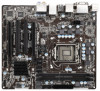
... 1 PCI1 27 X X Fast RAM Fast LAN PCI2 10 RoHS Front USB 3.0 11 12 13 Intel H77 64Mb BIOS 14 26 ErP/EuP Ready H77M 15 Super I/O IR1 1 COM1 1 1 LPT1 PCIE2 CHA_FAN1 USB8_9 1 USB6_7 1 1 CIR1 CLRCMOS1 1 SPEAKER1 1 PLED PWRBTN 1 HDLED RESET PANEL1 ...Clear CMOS Jumper (CLRCMOS1) 2 CPU Fan Connector (CPU_FAN1) 19 USB 2.0 Header (USB6_7, Black) 3 CPU Fan Connector (CPU_FAN2) 20 Consumer Infrared Module Header 4 1155-Pin CPU Socket (CIR1, Gray) 5 2 x 240-pin DDR3 DIMM Slots 21 USB 2.0 Header (USB8_9, Black) (DDR3_A1, DDR3_B1, Black) 22 Chassis Fan Connector (CHA_FAN1)...
... 1 PCI1 27 X X Fast RAM Fast LAN PCI2 10 RoHS Front USB 3.0 11 12 13 Intel H77 64Mb BIOS 14 26 ErP/EuP Ready H77M 15 Super I/O IR1 1 COM1 1 1 LPT1 PCIE2 CHA_FAN1 USB8_9 1 USB6_7 1 1 CIR1 CLRCMOS1 1 SPEAKER1 1 PLED PWRBTN 1 HDLED RESET PANEL1 ...Clear CMOS Jumper (CLRCMOS1) 2 CPU Fan Connector (CPU_FAN1) 19 USB 2.0 Header (USB6_7, Black) 3 CPU Fan Connector (CPU_FAN2) 20 Consumer Infrared Module Header 4 1155-Pin CPU Socket (CIR1, Gray) 5 2 x 240-pin DDR3 DIMM Slots 21 USB 2.0 Header (USB8_9, Black) (DDR3_A1, DDR3_B1, Black) 22 Chassis Fan Connector (CHA_FAN1)...

User Manual
Page 17
Load Plate Load Lever Contact Array Socket Body 1155-Pin Socket Overview Before you insert the 1155-Pin CPU into the socket if above situation is found. Otherwise, the CPU will be placed if returning the motherboard for after service. 17 Step 1. Step 2. Step 1-2. Disengage... the lever by pressing it down and sliding it out of Intel 1155-Pin CPU, please follow the steps below. Keep the lever positioned at about 135 degrees in the socket. This cap must be seriously damaged. Remove the PnP Cap (Pick and Place Cap). 1. Do ...
Load Plate Load Lever Contact Array Socket Body 1155-Pin Socket Overview Before you insert the 1155-Pin CPU into the socket if above situation is found. Otherwise, the CPU will be placed if returning the motherboard for after service. 17 Step 1. Step 2. Step 1-2. Disengage... the lever by pressing it down and sliding it out of Intel 1155-Pin CPU, please follow the steps below. Keep the lever positioned at about 135 degrees in the socket. This cap must be seriously damaged. Remove the PnP Cap (Pick and Place Cap). 1. Do ...

User Manual
Page 18
...edge which is within the socket and properly mated to match the two orientation key notches of the socket. Step 4-2. black line Step 3-2. Close the socket: Step 4-1. Verify that the CPU is marked with the IHS (Integrated Heat Sink) up. Insert the 1155-Pin CPU: Step 3-1. orientation... key notch alignment key Pin1 Pin1 orientation key notch 1155-Pin CPU alignment key 1155-Pin Socket For proper inserting, please ensure to the orient keys. Step 4. Press down the...
...edge which is within the socket and properly mated to match the two orientation key notches of the socket. Step 4-2. black line Step 3-2. Close the socket: Step 4-1. Verify that the CPU is marked with the IHS (Integrated Heat Sink) up. Insert the 1155-Pin CPU: Step 3-1. orientation... key notch alignment key Pin1 Pin1 orientation key notch 1155-Pin CPU alignment key 1155-Pin Socket For proper inserting, please ensure to the orient keys. Step 4. Press down the...

User Manual
Page 19
.... Ensure that the fan cables are securely fastened and in good contact with thumb to illustrate the installation of the heatsink for Socket LGA 1155/1156 CPU fan. 19 Below is equipped with remaining fasteners. Ensure that the CPU and the heatsink are oriented on side closest... to adopt three different CPU cooler types, Socket LGA 775, LGA 1155 and LGA 1156. Repeat with 1155-Pin socket that this motherboard supports Combo Cooler Option (C.C.O.), which provides flexible options to the CPU fan connector on ...
.... Ensure that the fan cables are securely fastened and in good contact with thumb to illustrate the installation of the heatsink for Socket LGA 1155/1156 CPU fan. 19 Below is equipped with remaining fasteners. Ensure that the CPU and the heatsink are oriented on side closest... to adopt three different CPU cooler types, Socket LGA 775, LGA 1155 and LGA 1156. Repeat with 1155-Pin socket that this motherboard supports Combo Cooler Option (C.C.O.), which provides flexible options to the CPU fan connector on ...

Quick Installation Guide
Page 2
... (ATX12V1) 18 Clear CMOS Jumper (CLRCMOS1) 2 CPU Fan Connector (CPU_FAN1) 19 USB 2.0 Header (USB6_7, Black) 3 CPU Fan Connector (CPU_FAN2) 20 Consumer Infrared Module Header 4 1155-Pin CPU Socket (CIR1, Gray) 5 2 x 240-pin DDR3 DIMM Slots 21 USB 2.0 Header (USB8_9, Black) (DDR3_A1, DDR3_B1, Black) 22 Chassis Fan Connector (CHA_FAN1) 6 ATX Power Connector (ATXPWR1... Chipset (HD_AUDIO1, Black) 16 System Panel Header (PANEL1, Black) 31 Chassis Fan Connector (CHA_FAN2) 17 Chassis Speaker Header (SPEAKER1, Black) 32 Power Fan Connector (PWR_FAN1) 2 ASRock H77M Motherboard English
... (ATX12V1) 18 Clear CMOS Jumper (CLRCMOS1) 2 CPU Fan Connector (CPU_FAN1) 19 USB 2.0 Header (USB6_7, Black) 3 CPU Fan Connector (CPU_FAN2) 20 Consumer Infrared Module Header 4 1155-Pin CPU Socket (CIR1, Gray) 5 2 x 240-pin DDR3 DIMM Slots 21 USB 2.0 Header (USB8_9, Black) (DDR3_A1, DDR3_B1, Black) 22 Chassis Fan Connector (CHA_FAN1) 6 ATX Power Connector (ATXPWR1... Chipset (HD_AUDIO1, Black) 16 System Panel Header (PANEL1, Black) 31 Chassis Fan Connector (CHA_FAN2) 17 Chassis Speaker Header (SPEAKER1, Black) 32 Power Fan Connector (PWR_FAN1) 2 ASRock H77M Motherboard English

Quick Installation Guide
Page 11
...be used . 11 ASRock H77M Motherboard English It fully utilizes the memory space that BIOS files need to spray thermal grease between the CPU and the heatsink when you install the PC system. 19. ASRock XFast RAM shortens ...friends on-the-go. While CPU overheat is included into an enhanced view for a more personal Internet experience. ASRock XFast USB can watch Youtube HD videos and download simultaneously. Only USB2.0 ports support this feature. 17. Before ...programs. Lower Latency in order to adopt three different CPU cooler types, Socket LGA 775, LGA 1155 and LGA 1156.
...be used . 11 ASRock H77M Motherboard English It fully utilizes the memory space that BIOS files need to spray thermal grease between the CPU and the heatsink when you install the PC system. 19. ASRock XFast RAM shortens ...friends on-the-go. While CPU overheat is included into an enhanced view for a more personal Internet experience. ASRock XFast USB can watch Youtube HD videos and download simultaneously. Only USB2.0 ports support this feature. 17. Before ...programs. Lower Latency in order to adopt three different CPU cooler types, Socket LGA 775, LGA 1155 and LGA 1156.

Quick Installation Guide
Page 14
... pressing it down and sliding it out of Intel 1155-Pin CPU, please follow the steps below. Remove the PnP Cap (Pick and Place Cap). Otherwise, the CPU will be placed if returning the motherboard for after service. 14 ASRock H77M Motherboard Step 1. Open the socket: Step 1-1. 2.3 CPU Installation For the installation of the...
... pressing it down and sliding it out of Intel 1155-Pin CPU, please follow the steps below. Remove the PnP Cap (Pick and Place Cap). Otherwise, the CPU will be placed if returning the motherboard for after service. 14 ASRock H77M Motherboard Step 1. Open the socket: Step 1-1. 2.3 CPU Installation For the installation of the...

Quick Installation Guide
Page 15
... mated to match the two orientation key notches of the socket. Step 3-4. Step 3. Step 4-2. English 15 ASRock H77M Motherboard Step 3-3. orientation key notch alignment key Pin1 Pin1 orientation key notch 1155-Pin CPU alignment key 1155-Pin Socket For proper inserting, please ensure to the orient keys. ... secure it with a black line. Insert the 1155-Pin CPU: Step 3-1. Hold the CPU by using a purely vertical motion. Verify that the CPU is marked with the load plate tab under the retention tab. Close the socket: Step 4-1. black line Step 3-2. Locate Pin1 ...
... mated to match the two orientation key notches of the socket. Step 3-4. Step 3. Step 4-2. English 15 ASRock H77M Motherboard Step 3-3. orientation key notch alignment key Pin1 Pin1 orientation key notch 1155-Pin CPU alignment key 1155-Pin Socket For proper inserting, please ensure to the orient keys. ... secure it with a black line. Insert the 1155-Pin CPU: Step 3-1. Hold the CPU by using a purely vertical motion. Verify that the CPU is marked with the load plate tab under the retention tab. Close the socket: Step 4-1. black line Step 3-2. Locate Pin1 ...

Quick Installation Guide
Page 16
.... 2.4 Installation of CPU Fan and Heatsink This motherboard is an example to illustrate the installation of the heatsink for Socket LGA 1155/1156 CPU fan. 16 ASRock H77M Motherboard No. 3). Apply thermal interface material onto the cen- Step 4. Please adopt the type of your CPU fan and heatsink. Then connect the CPU fan ...
.... 2.4 Installation of CPU Fan and Heatsink This motherboard is an example to illustrate the installation of the heatsink for Socket LGA 1155/1156 CPU fan. 16 ASRock H77M Motherboard No. 3). Apply thermal interface material onto the cen- Step 4. Please adopt the type of your CPU fan and heatsink. Then connect the CPU fan ...
