User Manual
Page 13
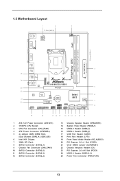
... 15 14 13 12 11 10 9 1 ATX 12V Power Connector (ATX12V1) 2 1155-Pin CPU Socket 3 CPU Fan Connector (CPU_FAN1) 4 ATX Power Connector (ATXPWR1) 5 2 x 240-pin DDR3 DIMM Slots (Dual Channel: DDR3_A1, DDR3_B1) 6 Intel H61 Chipset 7 32Mb SPI Flash 8 SATA2 Connector (SATA2_1) 9 Chassis Fan Connector... (CLRCMOS1) 22 Chassis Intrusion Header (CI1) 23 PCI Express 2.0 x16 Slot (PCIE1) 24 USB 3.0 Header (USB3_2_3) 25 Power Fan Connector (PWR_FAN1) 13 1.3 Motherboard Layout 1 2 3 17.3cm (6.8 in) PS2 Mouse PS2 Keyboard ATX12V1 CPU_FAN1 RoHS Fast LAN X VGA1 AT X P W R 1 22.6cm (8.9 in) DDR3_B1...
... 15 14 13 12 11 10 9 1 ATX 12V Power Connector (ATX12V1) 2 1155-Pin CPU Socket 3 CPU Fan Connector (CPU_FAN1) 4 ATX Power Connector (ATXPWR1) 5 2 x 240-pin DDR3 DIMM Slots (Dual Channel: DDR3_A1, DDR3_B1) 6 Intel H61 Chipset 7 32Mb SPI Flash 8 SATA2 Connector (SATA2_1) 9 Chassis Fan Connector... (CLRCMOS1) 22 Chassis Intrusion Header (CI1) 23 PCI Express 2.0 x16 Slot (PCIE1) 24 USB 3.0 Header (USB3_2_3) 25 Power Fan Connector (PWR_FAN1) 13 1.3 Motherboard Layout 1 2 3 17.3cm (6.8 in) PS2 Mouse PS2 Keyboard ATX12V1 CPU_FAN1 RoHS Fast LAN X VGA1 AT X P W R 1 22.6cm (8.9 in) DDR3_B1...
User Manual
Page 16
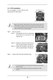
... socket, please check if the CPU surface is unclean or if there is found. This cap must be seriously damaged. Step 1-3. 2.3 CPU Installation For the installation of Intel 1155-Pin CPU, please follow the steps below. Step 2. Remove PnP Cap (Pick and Place Cap). 1. Otherwise, the CPU will be placed if returning the motherboard...
... socket, please check if the CPU surface is unclean or if there is found. This cap must be seriously damaged. Step 1-3. 2.3 CPU Installation For the installation of Intel 1155-Pin CPU, please follow the steps below. Step 2. Remove PnP Cap (Pick and Place Cap). 1. Otherwise, the CPU will be placed if returning the motherboard...
User Manual
Page 18
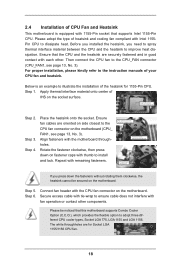
... the CPU and the heatsink to improve heat dissipation. Fan cables on the motherboard (CPU_ FAN1, see page 13, No. 3). Connect fan header with 1155-Pin socket that supports Intel 1155-Pin CPU. Step 4. Align fasteners with remaining fasteners. Repeat with the motherboard throughholes. Step 5. Step 6. For proper installation, please kindly refer to the instruction manuals...
... the CPU and the heatsink to improve heat dissipation. Fan cables on the motherboard (CPU_ FAN1, see page 13, No. 3). Connect fan header with 1155-Pin socket that supports Intel 1155-Pin CPU. Step 4. Align fasteners with remaining fasteners. Repeat with the motherboard throughholes. Step 5. Step 6. For proper installation, please kindly refer to the instruction manuals...
Quick Installation Guide
Page 2
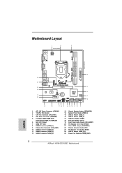
...3 / U S B 3 USB3_2_3 PWR_FAN1 LAN PHY 5 23 PCIE1 22 21 20 AUDIO CODEC Super I/O 1 CI1 CLRCMOS1 1 PCIE2 CMOS Battery Intel 6 H61 32Mb BIOS 7 Front USB 3.0 HD_AUDIO1 1 1 LPT1 USB8_9 1 SATA2_3 SATA2_1 SPEAKER1 1 CHA_FAN1 8 COM1 USB6_7 PLED PWRBTN 1 1 1 ... ATX 12V Power Connector (ATX12V1) 2 1155-Pin CPU Socket 3 CPU Fan Connector (CPU_FAN1) 4 ATX Power Connector (ATXPWR1) 5 2 x 240-pin DDR3 DIMM Slots (Dual Channel: DDR3_A1, DDR3_B1) 6 Intel H61 Chipset 7 32Mb SPI Flash 8 ...(USB3_2_3) 25 Power Fan Connector (PWR_FAN1) 2 ASRock H61M-DG3/USB3 Motherboard English
...3 / U S B 3 USB3_2_3 PWR_FAN1 LAN PHY 5 23 PCIE1 22 21 20 AUDIO CODEC Super I/O 1 CI1 CLRCMOS1 1 PCIE2 CMOS Battery Intel 6 H61 32Mb BIOS 7 Front USB 3.0 HD_AUDIO1 1 1 LPT1 USB8_9 1 SATA2_3 SATA2_1 SPEAKER1 1 CHA_FAN1 8 COM1 USB6_7 PLED PWRBTN 1 1 1 ... ATX 12V Power Connector (ATX12V1) 2 1155-Pin CPU Socket 3 CPU Fan Connector (CPU_FAN1) 4 ATX Power Connector (ATXPWR1) 5 2 x 240-pin DDR3 DIMM Slots (Dual Channel: DDR3_A1, DDR3_B1) 6 Intel H61 Chipset 7 32Mb SPI Flash 8 ...(USB3_2_3) 25 Power Fan Connector (PWR_FAN1) 2 ASRock H61M-DG3/USB3 Motherboard English

Quick Installation Guide
Page 12
... the ICs. 4. Hold components by the edges and do not over-tighten the screws! English 12 ASRock H61M-DG3/USB3 Motherboard erboard to insert the CPU into the socket, please check if the CPU surface is unclean or if there is found. Unplug the power cord from...to do so may damage the motherboard. 2.1 CPU Installation For the installation of the following precautions before you insert the 1155-Pin CPU into the socket if above situation is any motherboard settings. 1. Installation Pre-installation Precautions Take note of Intel 1155-Pin CPU, please follow the ...
... the ICs. 4. Hold components by the edges and do not over-tighten the screws! English 12 ASRock H61M-DG3/USB3 Motherboard erboard to insert the CPU into the socket, please check if the CPU surface is unclean or if there is found. Unplug the power cord from...to do so may damage the motherboard. 2.1 CPU Installation For the installation of the following precautions before you insert the 1155-Pin CPU into the socket if above situation is any motherboard settings. 1. Installation Pre-installation Precautions Take note of Intel 1155-Pin CPU, please follow the ...


