User Manual
Page 12
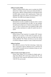
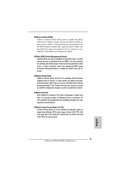
... from bypassing OMG, guest accounts without entering Windows® OS. ASRock Combo Cooler Option (C.C.O.) Combo Cooler Option (C.C.O.) provides the flexible option.... If power loss occurs during the BIOS update process, ASRock Crashless BIOS will completely change your USB disk. You may...at specified times via OMG. ASRock OMG (Online Management Guard) Administrators are required. ASRock Fast Boot With ASRock's exclusive Fast Boot technology, ...775 and 1156 CPU Fan can autodetect the latest UEFI from our servers. No more waiting! ASRock Internet Flash ASRock Internet Flash ...
... from bypassing OMG, guest accounts without entering Windows® OS. ASRock Combo Cooler Option (C.C.O.) Combo Cooler Option (C.C.O.) provides the flexible option.... If power loss occurs during the BIOS update process, ASRock Crashless BIOS will completely change your USB disk. You may...at specified times via OMG. ASRock OMG (Online Management Guard) Administrators are required. ASRock Fast Boot With ASRock's exclusive Fast Boot technology, ...775 and 1156 CPU Fan can autodetect the latest UEFI from our servers. No more waiting! ASRock Internet Flash ASRock Internet Flash ...
User Manual
Page 13
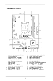
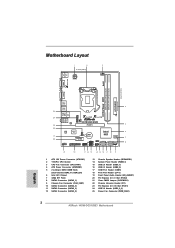
... PLED PWRBTN CHA_FAN1 8 1 1 1 HDLED RESET PANEL1 SATA2_2 SATA2_0 19 18 17 16 15 14 13 12 11 10 9 1 ATX 12V Power Connector (ATX12V1) 2 1155-Pin CPU Socket 3 CPU Fan Connector (CPU_FAN1) 4 ATX Power Connector (ATXPWR1) 5 2 x 240-pin DDR3 DIMM Slots (Dual Channel: DDR3_A1, DDR3_B1) 6 Intel H61 Chipset 7 32Mb SPI Flash 8 SATA2 Connector (SATA2_1...
... PLED PWRBTN CHA_FAN1 8 1 1 1 HDLED RESET PANEL1 SATA2_2 SATA2_0 19 18 17 16 15 14 13 12 11 10 9 1 ATX 12V Power Connector (ATX12V1) 2 1155-Pin CPU Socket 3 CPU Fan Connector (CPU_FAN1) 4 ATX Power Connector (ATXPWR1) 5 2 x 240-pin DDR3 DIMM Slots (Dual Channel: DDR3_A1, DDR3_B1) 6 Intel H61 Chipset 7 32Mb SPI Flash 8 SATA2 Connector (SATA2_1...
User Manual
Page 16
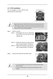
... the lever by depressing down and out on the socket. Step 1-3. Remove PnP Cap (Pick and Place Cap). 1. Load Plate Load Lever Contact Array Socket Body 1155-Pin Socket Overview Before you insert the 1155-Pin CPU into the socket if above situation is recommended to use the cap ...retention tab. Step 2. Step 1. Rotate the load plate to fully open position at approximately 135 degrees. Step 1-2. Open the socket: Step 1-1. Otherwise, the CPU will be placed if returning the motherboard for after service. 16 It is found. Rotate the load lever to fully open ...
... the lever by depressing down and out on the socket. Step 1-3. Remove PnP Cap (Pick and Place Cap). 1. Load Plate Load Lever Contact Array Socket Body 1155-Pin Socket Overview Before you insert the 1155-Pin CPU into the socket if above situation is recommended to use the cap ...retention tab. Step 2. Step 1. Rotate the load plate to fully open position at approximately 135 degrees. Step 1-2. Open the socket: Step 1-1. Otherwise, the CPU will be placed if returning the motherboard for after service. 16 It is found. Rotate the load lever to fully open ...
User Manual
Page 17
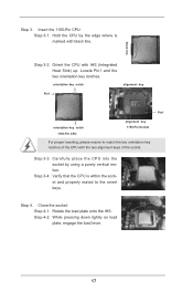
... alignment key Pin1 Pin1 orientation key notch 1155-Pin CPU alignment key 1155-Pin Socket For proper inserting, please ensure to the orient keys. Step 4. Step 4-2. Carefully place the CPU into the socket by the edge where is within the socket and properly mated to match the two orientation key ...notches of the CPU with the two alignment keys of the socket. Rotate the load plate onto the IHS. Step 3-4. Insert ...
... alignment key Pin1 Pin1 orientation key notch 1155-Pin CPU alignment key 1155-Pin Socket For proper inserting, please ensure to the orient keys. Step 4. Step 4-2. Carefully place the CPU into the socket by the edge where is within the socket and properly mated to match the two orientation key ...notches of the CPU with the two alignment keys of the socket. Rotate the load plate onto the IHS. Step 3-4. Insert ...
User Manual
Page 18
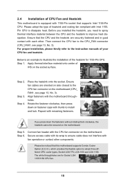
...or contact other . Step 4. Place the heatsink onto the socket. Align fasteners with remaining fasteners. Connect fan header with the CPU fan connector on fastener caps with 1155-Pin socket that supports Intel 1155-Pin CPU. Below is equipped with thumb to install and lock. Rotate ... tie-wrap to improve heat dissipation. Please be secured on the socket surface. Ensure that this motherboard supports Combo Cooler Option (C.C.O.), which provides the flexible option to adopt three different CPU cooler types, Socket LGA 775, LGA 1155 and LGA 1156. Step 1. Apply thermal...
...or contact other . Step 4. Place the heatsink onto the socket. Align fasteners with remaining fasteners. Connect fan header with the CPU fan connector on fastener caps with 1155-Pin socket that supports Intel 1155-Pin CPU. Below is equipped with thumb to install and lock. Rotate ... tie-wrap to improve heat dissipation. Please be secured on the socket surface. Ensure that this motherboard supports Combo Cooler Option (C.C.O.), which provides the flexible option to adopt three different CPU cooler types, Socket LGA 775, LGA 1155 and LGA 1156. Step 1. Apply thermal...
Quick Installation Guide
Page 2
... 1 HDLED RESET PANEL1 SATA2_2 SATA2_0 19 18 17 16 15 14 13 12 11 10 9 1 ATX 12V Power Connector (ATX12V1) 2 1155-Pin CPU Socket 3 CPU Fan Connector (CPU_FAN1) 4 ATX Power Connector (ATXPWR1) 5 2 x 240-pin DDR3 DIMM Slots (Dual Channel: DDR3_A1, DDR3_B1) 6 Intel H61 Chipset... (CLRCMOS1) 22 Chassis Intrusion Header (CI1) 23 PCI Express 2.0 x16 Slot (PCIE1) 24 USB 3.0 Header (USB3_2_3) 25 Power Fan Connector (PWR_FAN1) 2 ASRock H61M-DG3/USB3 Motherboard English Motherboard Layout 1 2 17.3cm (6.8 in) ATX12V1 3 CPU_FAN1 PS2 Mouse PS2 Keyboard RoHS Fast LAN X VGA1 AT X P W R 1 22...
... 1 HDLED RESET PANEL1 SATA2_2 SATA2_0 19 18 17 16 15 14 13 12 11 10 9 1 ATX 12V Power Connector (ATX12V1) 2 1155-Pin CPU Socket 3 CPU Fan Connector (CPU_FAN1) 4 ATX Power Connector (ATXPWR1) 5 2 x 240-pin DDR3 DIMM Slots (Dual Channel: DDR3_A1, DDR3_B1) 6 Intel H61 Chipset... (CLRCMOS1) 22 Chassis Intrusion Header (CI1) 23 PCI Express 2.0 x16 Slot (PCIE1) 24 USB 3.0 Header (USB3_2_3) 25 Power Fan Connector (PWR_FAN1) 2 ASRock H61M-DG3/USB3 Motherboard English Motherboard Layout 1 2 17.3cm (6.8 in) ATX12V1 3 CPU_FAN1 PS2 Mouse PS2 Keyboard RoHS Fast LAN X VGA1 AT X P W R 1 22...
Quick Installation Guide
Page 11
... BIOS will completely change your USB disk. Please note that you must be used. 11 ASRock H61M-DG3/USB3 Motherboard English ASRock Fast Boot With ASRock's exclusive Fast Boot technology, it takes less than 1.5 seconds to logon to enable this feature. In other users. No more waiting! Only USB2.0 ports ... to be noticed that BIOS files need to establish an internet curfew or restrict internet access at specified times via OMG. ASRock Crashless BIOS ASRock Crashless BIOS allows users to adopt three different CPU cooler types, Socket LGA 775, LGA 1155 and LGA 1156.
... BIOS will completely change your USB disk. Please note that you must be used. 11 ASRock H61M-DG3/USB3 Motherboard English ASRock Fast Boot With ASRock's exclusive Fast Boot technology, it takes less than 1.5 seconds to logon to enable this feature. In other users. No more waiting! Only USB2.0 ports ... to be noticed that BIOS files need to establish an internet curfew or restrict internet access at specified times via OMG. ASRock Crashless BIOS ASRock Crashless BIOS allows users to adopt three different CPU cooler types, Socket LGA 775, LGA 1155 and LGA 1156.

Quick Installation Guide
Page 12
... you uninstall any motherboard settings. 1. Hold components by the edges and do not over-tighten the screws! Load Plate Contact Array Load Lever Socket Body 1155-Pin Socket Overview Before you handle components. 3. English 12 ASRock H61M-DG3/USB3 Motherboard Otherwise, the CPU will be seriously damaged. Installation Pre-installation Precautions Take note of Intel 1155-Pin...
... you uninstall any motherboard settings. 1. Hold components by the edges and do not over-tighten the screws! Load Plate Contact Array Load Lever Socket Body 1155-Pin Socket Overview Before you handle components. 3. English 12 ASRock H61M-DG3/USB3 Motherboard Otherwise, the CPU will be seriously damaged. Installation Pre-installation Precautions Take note of Intel 1155-Pin...

Quick Installation Guide
Page 13
... at approximately 100 degrees. Locate Pin1 and the two orientation key notches. Step 1. Insert the 1155-Pin CPU: Step 3-1. black line Step 3-2. Step 3. Orient the CPU with the two alignment keys of the socket. 13 ASRock H61M-DG3/USB3 Motherboard English Disengaging the lever by the edges where are marked with black lines. It is recommended to...
... at approximately 100 degrees. Locate Pin1 and the two orientation key notches. Step 1. Insert the 1155-Pin CPU: Step 3-1. black line Step 3-2. Step 3. Orient the CPU with the two alignment keys of the socket. 13 ASRock H61M-DG3/USB3 Motherboard English Disengaging the lever by the edges where are marked with black lines. It is recommended to...

Quick Installation Guide
Page 14
... lever. Secure excess cable with tie-wrap to the instruction manuals of the heatsink for Socket LGA 1155/1156 CPU fan. 14 ASRock H61M-DG3/USB3 Motherboard English Step 3-4. Below is within the socket and properly mated to adopt three different CPU cooler types, Socket LGA 775, LGA 1155 and LGA 1156. Rotate the fastener clockwise, then press down...
... lever. Secure excess cable with tie-wrap to the instruction manuals of the heatsink for Socket LGA 1155/1156 CPU fan. 14 ASRock H61M-DG3/USB3 Motherboard English Step 3-4. Below is within the socket and properly mated to adopt three different CPU cooler types, Socket LGA 775, LGA 1155 and LGA 1156. Rotate the fastener clockwise, then press down...


