Mining System Installation Guide
Page 1
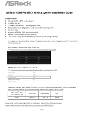
...users to visit the official website of the graphics card vendor to the following example. H110 Pro BTC+ with CPU + memory + SSD RX470 x Qty GTX1060 x Qty Total 250W 120W x 8 120W x 5 1810W Please refer to check the graphics card TDP. ASRock H110 Pro BTC+ mining system Installation Guide Configuration: 1. Link: http://www.amd.com/en-gb/... the system uses eight RX470 and five GTX1060, the total sum including other components is 1810W. Total power supply at least 2400W. ASRock H110 Pro BTC+ motherboard 2. 13 x PCIe riser kit 3. 13 x AMD / 8 x AMD + 5 x NVIDIA graphic cards. 4.
...users to visit the official website of the graphics card vendor to the following example. H110 Pro BTC+ with CPU + memory + SSD RX470 x Qty GTX1060 x Qty Total 250W 120W x 8 120W x 5 1810W Please refer to check the graphics card TDP. ASRock H110 Pro BTC+ mining system Installation Guide Configuration: 1. Link: http://www.amd.com/en-gb/... the system uses eight RX470 and five GTX1060, the total sum including other components is 1810W. Total power supply at least 2400W. ASRock H110 Pro BTC+ motherboard 2. 13 x PCIe riser kit 3. 13 x AMD / 8 x AMD + 5 x NVIDIA graphic cards. 4.
User Manual
Page 7
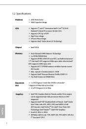
...) 2.0 • 15μ Gold Contact in DIMM Slots Expansion Slot • 1 x PCI Express 3.0 x16 Slot (PCIE2: x16 mode)* * Supports NVMe SSD as boot disk • 12 x PCI Express 2.0 x1 Slots English Graphics • Intel® HD Graphics Built-in Visuals and the VGA outputs can be...CPU up to 91W • Digi Power design • 8 Power Phase design • Supports Intel® Turbo Boost 2.0 Technology Chipset • Intel® H110 Memory • Dual Channel DDR4 Memory Technology • 2 x DDR4 DIMM Slots • Supports DDR4 2400/2133 non-ECC, un-buffered memory* * 7th Gen...
...) 2.0 • 15μ Gold Contact in DIMM Slots Expansion Slot • 1 x PCI Express 3.0 x16 Slot (PCIE2: x16 mode)* * Supports NVMe SSD as boot disk • 12 x PCI Express 2.0 x1 Slots English Graphics • Intel® HD Graphics Built-in Visuals and the VGA outputs can be...CPU up to 91W • Digi Power design • 8 Power Phase design • Supports Intel® Turbo Boost 2.0 Technology Chipset • Intel® H110 Memory • Dual Channel DDR4 Memory Technology • 2 x DDR4 DIMM Slots • Supports DDR4 2400/2133 non-ECC, un-buffered memory* * 7th Gen...

User Manual
Page 30
D C B A E D C B A C B A H110 Pro BTC+ Step 3 Move the standoff based on the nut to use the default nut. Skip Step 3 and 4 and go straight to Step 5 if you are going to be aware that the M.2 (NGFF) SSD module only fits in one orientation. Step 5 Align and gently insert the M.2 (NGFF) SSD module into the desired nut location on...
D C B A E D C B A C B A H110 Pro BTC+ Step 3 Move the standoff based on the nut to use the default nut. Skip Step 3 and 4 and go straight to Step 5 if you are going to be aware that the M.2 (NGFF) SSD module only fits in one orientation. Step 5 Align and gently insert the M.2 (NGFF) SSD module into the desired nut location on...

Quick Installation Guide
Page 8
... 2.0 • 15μ Gold Contact in DIMM Slots Expansion Slot • 1 x PCI Express 3.0 x16 Slot (PCIE2: x16 mode)* * Supports NVMe SSD as boot disk • 12 x PCI Express 2.0 x1 Slots Graphics • Intel® HD Graphics Built-in Visuals and the VGA outputs can be supported...CPU up to 91W • Digi Power design • 8 Power Phase design • Supports Intel® Turbo Boost 2.0 Technology Chipset • Intel® H110 Memory • Dual Channel DDR4 Memory Technology • 2 x DDR4 DIMM Slots • Supports DDR4 2400/2133 non-ECC, un-buffered memory* * 7th Gen...
... 2.0 • 15μ Gold Contact in DIMM Slots Expansion Slot • 1 x PCI Express 3.0 x16 Slot (PCIE2: x16 mode)* * Supports NVMe SSD as boot disk • 12 x PCI Express 2.0 x1 Slots Graphics • Intel® HD Graphics Built-in Visuals and the VGA outputs can be supported...CPU up to 91W • Digi Power design • 8 Power Phase design • Supports Intel® Turbo Boost 2.0 Technology Chipset • Intel® H110 Memory • Dual Channel DDR4 Memory Technology • 2 x DDR4 DIMM Slots • Supports DDR4 2400/2133 non-ECC, un-buffered memory* * 7th Gen...

Quick Installation Guide
Page 27
D C B A D C B A C B A H110 Pro BTC+ Step 3 Move the standoff based on the motherboard. Step 4 Peel off the yellow protective film on the nut to use the default nut. Otherwise, release ... default. The standoff is placed at the nut location A by hand. Hand tighten the standoff into the M.2 slot. Step 5 Align and gently insert the M.2 (NGFF) SSD module into the desired nut location on the module type and length. C B A English 25 Please be used. Skip Step 3 and 4 and go straight to Step...
D C B A D C B A C B A H110 Pro BTC+ Step 3 Move the standoff based on the motherboard. Step 4 Peel off the yellow protective film on the nut to use the default nut. Otherwise, release ... default. The standoff is placed at the nut location A by hand. Hand tighten the standoff into the M.2 slot. Step 5 Align and gently insert the M.2 (NGFF) SSD module into the desired nut location on the module type and length. C B A English 25 Please be used. Skip Step 3 and 4 and go straight to Step...
