
User Manual
Page 6
LGA 775 for Intel® CoreTM 2 Extreme / CoreTM 2 Quad / CoreTM 2 Duo / ...non-ECC, un-buffered memory (see CAUTION 3) - Intel® Graphics Media Accelerator 3100 - shared memory 384MB (see CAUTION 2) - G31M-S Realtek PCIE x1 LAN 8103EL / 8102EL, speed 10/100 Mb/s - Supports EM64T CPU - Southbridge: Intel® ICH7 - Pixel ... Supports CPU up to -Use USB 2.0 Ports - 1 x RJ-45 LAN Port with all FSB1600/1333/1066/800MHz CPUs (see CAUTION 1) - G31M-GS Realtek PCIE x 1 Gigabit LAN RTL8111DL, speed 10/100/1000 Mb/s - Dual Channel DDR2 Memory Technology (see CAUTION 6) - 1 x PCI Express...
LGA 775 for Intel® CoreTM 2 Extreme / CoreTM 2 Quad / CoreTM 2 Duo / ...non-ECC, un-buffered memory (see CAUTION 3) - Intel® Graphics Media Accelerator 3100 - shared memory 384MB (see CAUTION 2) - G31M-S Realtek PCIE x1 LAN 8103EL / 8102EL, speed 10/100 Mb/s - Supports EM64T CPU - Southbridge: Intel® ICH7 - Pixel ... Supports CPU up to -Use USB 2.0 Ports - 1 x RJ-45 LAN Port with all FSB1600/1333/1066/800MHz CPUs (see CAUTION 1) - G31M-GS Realtek PCIE x 1 Gigabit LAN RTL8111DL, speed 10/100/1000 Mb/s - Dual Channel DDR2 Memory Technology (see CAUTION 6) - 1 x PCI Express...

User Manual
Page 10
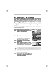
... Channel DDRII_1 (64 bit, 240-piFnSmBod8ul0e)0 DDRII_2 (64 bit, 240-piFnSmBod8ul0e)0 24.4cm (9.6 in) SATAII_3 SATAII_4 6 7 8 9 10 11 1 PS2_USB_PWR1 Jumper 16 USB 2.0 Header (USB6_7, Blue) 2 775-Pin CPU Socket 17 USB 2.0 Header (USB4_5, Blue) 3 North Bridge Controller 18 Chassis Fan Connector (CHA_FAN1) 4 CPU Fan Connector (CPU_FAN1) 19 Floppy Connector (FLOPPY1) 5 2 x 240...
... Channel DDRII_1 (64 bit, 240-piFnSmBod8ul0e)0 DDRII_2 (64 bit, 240-piFnSmBod8ul0e)0 24.4cm (9.6 in) SATAII_3 SATAII_4 6 7 8 9 10 11 1 PS2_USB_PWR1 Jumper 16 USB 2.0 Header (USB6_7, Blue) 2 775-Pin CPU Socket 17 USB 2.0 Header (USB4_5, Blue) 3 North Bridge Controller 18 Chassis Fan Connector (CHA_FAN1) 4 CPU Fan Connector (CPU_FAN1) 19 Floppy Connector (FLOPPY1) 5 2 x 240...
User Manual
Page 14
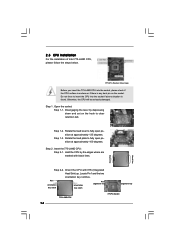
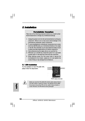
... the CPU by depressing down and out on the socket. Pin1 orientation key notch orientation key notch Pin1 alignment key alignment key 775-LAND CPU 14 775-Pin Socket black line black line Step 1-3. Locate Pin1 and the two orientation key notches. Do not force to insert the ... to fully open position at approximately 100 degrees. 2.3 CPU Installation For the installation of Intel 775-LAND CPU, please follow the steps below. 775-Pin Socket Overview Before you insert the 775-LAND CPU into the socket if above situation is any bent pin on the ShoockoetkMatrokedcCleoranerr retention tab...
... the CPU by depressing down and out on the socket. Pin1 orientation key notch orientation key notch Pin1 alignment key alignment key 775-LAND CPU 14 775-Pin Socket black line black line Step 1-3. Locate Pin1 and the two orientation key notches. Do not force to insert the ... to fully open position at approximately 100 degrees. 2.3 CPU Installation For the installation of Intel 775-LAND CPU, please follow the steps below. 775-Pin Socket Overview Before you insert the 775-LAND CPU into the socket if above situation is any bent pin on the ShoockoetkMatrokedcCleoranerr retention tab...
User Manual
Page 16
... connector (CPU_FAN1, see page 10, No. 4). For proper installation, please kindly refer to the instruction manuals of the heatsink for 775-LAND CPU. Place the heatsink onto the socket. Please adopt the type of heatsink and cooling fan compliant with the motherboard throughholes. ...Align fasteners with Intel 775-LAND CPU to dissipate heat. Connect fan header with thumb to install and lock. Rotate the fastener clockwise, then press down ...
... connector (CPU_FAN1, see page 10, No. 4). For proper installation, please kindly refer to the instruction manuals of the heatsink for 775-LAND CPU. Place the heatsink onto the socket. Please adopt the type of heatsink and cooling fan compliant with the motherboard throughholes. ...Align fasteners with Intel 775-LAND CPU to dissipate heat. Connect fan header with thumb to install and lock. Rotate the fastener clockwise, then press down ...
Quick Installation Guide
Page 2
... 16 USB 2.0 Header (USB6_7, Blue) 2 775-Pin CPU Socket 17 USB 2.0 Header (USB4_5, Blue) 3 North Bridge Controller 18 Chassis Fan Connector (CHA_FAN1) 4 CPU Fan Connector (CPU_FAN1) 19 Floppy Connector (FLOPPY1) 5 2 x 240-pin DDR2 DIMM Slots 20 EUP Audio Jumper (EUP_AUDIO1) (Dual Channel: DDRII_1, DDRII_2; Red) 2 ASRock G31M-GS / G31M-S Motherboard Yellow) 21 Front Panel Audio...
... 16 USB 2.0 Header (USB6_7, Blue) 2 775-Pin CPU Socket 17 USB 2.0 Header (USB4_5, Blue) 3 North Bridge Controller 18 Chassis Fan Connector (CHA_FAN1) 4 CPU Fan Connector (CPU_FAN1) 19 Floppy Connector (FLOPPY1) 5 2 x 240-pin DDR2 DIMM Slots 20 EUP Audio Jumper (EUP_AUDIO1) (Dual Channel: DDRII_1, DDRII_2; Red) 2 ASRock G31M-GS / G31M-S Motherboard Yellow) 21 Front Panel Audio...

Quick Installation Guide
Page 6
LGA 775 for Intel® CoreTM 2 Extreme / CoreTM 2 Quad / CoreTM 2 Duo / Pentium® Dual Core / Celeron® Dual Core / Celeron®, supporting Penryn Quad Core Yorkfield and Dual Core Wolfdale processors - Compatible with LED (ACT/LINK LED and SPEED LED) 6 ASRock G31M-GS / G31M-S .../2 Keyboard Port - 1 x Serial Port: COM1 - 1 x VGA Port - 4 x Ready-to 105W - Supports EM64T CPU - Max. G31M-GS Realtek PCIE x 1 Gigabit LAN RTL8111DL, speed 10/100/1000 Mb/s - G31M-S Realtek PCIE x1 LAN 8103EL / 8102EL, speed 10/100 Mb/s - Micro ATX Form Factor: 9.6-in x 7.2-in, 24.4 cm x 18...
LGA 775 for Intel® CoreTM 2 Extreme / CoreTM 2 Quad / CoreTM 2 Duo / Pentium® Dual Core / Celeron® Dual Core / Celeron®, supporting Penryn Quad Core Yorkfield and Dual Core Wolfdale processors - Compatible with LED (ACT/LINK LED and SPEED LED) 6 ASRock G31M-GS / G31M-S .../2 Keyboard Port - 1 x Serial Port: COM1 - 1 x VGA Port - 4 x Ready-to 105W - Supports EM64T CPU - Max. G31M-GS Realtek PCIE x 1 Gigabit LAN RTL8111DL, speed 10/100/1000 Mb/s - G31M-S Realtek PCIE x1 LAN 8103EL / 8102EL, speed 10/100 Mb/s - Micro ATX Form Factor: 9.6-in x 7.2-in, 24.4 cm x 18...
Quick Installation Guide
Page 10
Installation Pre-installation Precautions Take note of Intel 775-LAND CPU, please follow the steps below. 775-Pin Socket Overview Before you handle components. 3. Also remember to insert the CPU into the socket if above situation is any component. Whenever you... by the edges and do not over-tighten the screws! Otherwise, the CPU will be seriously damaged. 10 ASRock G31M-GS / G31M-S Motherboard English Unplug the power cord from the wall socket before you insert the 775-LAND CPU into the screw holes to secure the motherboard to the motherboard, peripherals, and/or components. 2....
Installation Pre-installation Precautions Take note of Intel 775-LAND CPU, please follow the steps below. 775-Pin Socket Overview Before you handle components. 3. Also remember to insert the CPU into the socket if above situation is any component. Whenever you... by the edges and do not over-tighten the screws! Otherwise, the CPU will be seriously damaged. 10 ASRock G31M-GS / G31M-S Motherboard English Unplug the power cord from the wall socket before you insert the 775-LAND CPU into the screw holes to secure the motherboard to the motherboard, peripherals, and/or components. 2....
Quick Installation Guide
Page 11
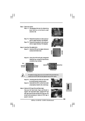
... 2-1. Locate Pin1 and the two orientation key notches. Pin1 orientation key notch orientation key notch Pin1 alignment key alignment key 775-LAND CPU 775-Pin Socket For proper inserting, please ensure to match the two orientation key notches of the CPU with right hand thumb ...Hold the CPU by the edges where are marked with IHS (Integrated Heat Sink) up. Rotate the load plate to assist in removal. 11 ASRock G31M-GS / G31M-S Motherboard English Step 2. Disengaging the lever by using a purely vertical motion. Orient the CPU with black lines. black line black line Step ...
... 2-1. Locate Pin1 and the two orientation key notches. Pin1 orientation key notch orientation key notch Pin1 alignment key alignment key 775-LAND CPU 775-Pin Socket For proper inserting, please ensure to match the two orientation key notches of the CPU with right hand thumb ...Hold the CPU by the edges where are marked with IHS (Integrated Heat Sink) up. Rotate the load plate to assist in removal. 11 ASRock G31M-GS / G31M-S Motherboard English Step 2. Disengaging the lever by using a purely vertical motion. Orient the CPU with black lines. black line black line Step ...

Quick Installation Guide
Page 12
...with remaining fasteners. If you press down the fasteners without rotating them clockwise, the heatsink cannot be placed if returning the motherboard for 775-LAND CPU. Secure excess cable with tie-wrap to ensure cable does not interfere with load plate tab under retention tab of load ...manuals of your CPU fan and heatsink. Close the socket: Step 4-1. Secure load lever with fan operation or contact other components. 12 ASRock G31M-GS / G31M-S Motherboard English Step 2. Ensure fan cables are oriented on side closest to illustrate the installation of IHS on the motherboard. Connect fan ...
...with remaining fasteners. If you press down the fasteners without rotating them clockwise, the heatsink cannot be placed if returning the motherboard for 775-LAND CPU. Secure excess cable with tie-wrap to ensure cable does not interfere with load plate tab under retention tab of load ...manuals of your CPU fan and heatsink. Close the socket: Step 4-1. Secure load lever with fan operation or contact other components. 12 ASRock G31M-GS / G31M-S Motherboard English Step 2. Ensure fan cables are oriented on side closest to illustrate the installation of IHS on the motherboard. Connect fan ...
