

User Manual
Page 8
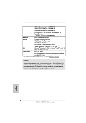
... Sensing - ErP/EuP Ready (ErP/EuP ready power supply is required) (see CAUTION 10) - Overclocking may affect your system stability, or even cause damage to the components and devices of your own risk and expense. ASRock XFast LAN (see CAUTION 13) - CPU Temperature Sensing Monitor - ASRock On/Off Play Technology (see CAUTION 12) - Microsoft...
... Sensing - ErP/EuP Ready (ErP/EuP ready power supply is required) (see CAUTION 10) - Overclocking may affect your system stability, or even cause damage to the components and devices of your own risk and expense. ASRock XFast LAN (see CAUTION 13) - CPU Temperature Sensing Monitor - ASRock On/Off Play Technology (see CAUTION 12) - Microsoft...

User Manual
Page 11
...system shall be noted that if you checking with the power supply manufacturer for the completed system. To meet EuP standard, please disable ASRock On/Off Play Technology rst. 11 For EuP ready power supply selection, we recommend you enable ASRock On/Off Play Technology, your system will not meet... EuP standard. Besides, please be under 100 mA current consumption. To meet EuP standard, an EuP ready motherboard and an EuP ready power supply are required. According to...
...system shall be noted that if you checking with the power supply manufacturer for the completed system. To meet EuP standard, please disable ASRock On/Off Play Technology rst. 11 For EuP ready power supply selection, we recommend you enable ASRock On/Off Play Technology, your system will not meet... EuP standard. Besides, please be under 100 mA current consumption. To meet EuP standard, an EuP ready motherboard and an EuP ready power supply are required. According to...

User Manual
Page 15
... Before you handle components. 3. Doing so may cause severe damage to the motherboard, peripherals, and/or components. 1. Unplug the power cord from the power supply. Also remember to static electricity, NEVER place your chassis to the chassis, please do not over-tighten the screws! To avoid ...2. 2. Installation This is detached from the wall socket before you install or remove any component, ensure that the power is switched off or the power cord is a Mini-ITX form factor (6.7-in x 6.7-in the bag that the motherboard ts into the screw holes to secure the motherboard...
... Before you handle components. 3. Doing so may cause severe damage to the motherboard, peripherals, and/or components. 1. Unplug the power cord from the power supply. Also remember to static electricity, NEVER place your chassis to the chassis, please do not over-tighten the screws! To avoid ...2. 2. Installation This is detached from the wall socket before you install or remove any component, ensure that the power is switched off or the power cord is a Mini-ITX form factor (6.7-in x 6.7-in the bag that the motherboard ts into the screw holes to secure the motherboard...

User Manual
Page 17
... same brand, speed, size and chiptype) memory modules in one memory module or two non-identical memory modules, it will cause permanent damage to disconnect power supply before adding or removing DIMMs or the system components.
... same brand, speed, size and chiptype) memory modules in one memory module or two non-identical memory modules, it will cause permanent damage to disconnect power supply before adding or removing DIMMs or the system components.

User Manual
Page 18
... Step 1. Step 2. Step 6. 2.4 Expansion Slot (PCI Express Slot) There is already installed in a chassis). Remove the bracket facing the slot that the power supply is switched off or the power cord is used for PCI Express x16 lane width graphics cards. Replace the system cover. 18 PCIE Slot: PCIE1 (PCIE x16 slot; Blue...
... Step 1. Step 2. Step 6. 2.4 Expansion Slot (PCI Express Slot) There is already installed in a chassis). Remove the bracket facing the slot that the power supply is switched off or the power cord is used for PCI Express x16 lane width graphics cards. Replace the system cover. 18 PCIE Slot: PCIE1 (PCIE x16 slot; Blue...

User Manual
Page 25
... to short pin2 and pin3 on CLRCMOS1 for 15 seconds, use a jumper cap to default setup, please turn off the computer and unplug the power cord from the power supply. The illustration shows a 3-pin jumper whose pin1 and pin2 are setup. After waiting for 5 seconds. 2.8 Jumpers Setup The illustration shows how jumpers are...
... to short pin2 and pin3 on CLRCMOS1 for 15 seconds, use a jumper cap to default setup, please turn off the computer and unplug the power cord from the power supply. The illustration shows a 3-pin jumper whose pin1 and pin2 are setup. After waiting for 5 seconds. 2.8 Jumpers Setup The illustration shows how jumpers are...

User Manual
Page 28
... 1-3 Connected 3-Pin Fan Installation (3-pin CPU_FAN2) (see p.12 No. 2) GND +12V CPU_FAN_SPEED ATX Power Connector 24 (24-pin ATXPWR1) (see p.12 No. 3) 12 13 Please connect an ATX power supply to the ground pin. Chassis Speaker Header (4-pin SPEAKER 1) (see p.12 No. 4) Chassis Fan Connector...matched correctly. If you adopt a traditional 20-pin ATX power supply. When connecting your power supply along with Pin 1 and Pin 13. 24 13 20-Pin ATX Power Supply Installation 12 1 28 To use the 20-pin ATX power supply, please plug your chassis front panel module to the ground...
... 1-3 Connected 3-Pin Fan Installation (3-pin CPU_FAN2) (see p.12 No. 2) GND +12V CPU_FAN_SPEED ATX Power Connector 24 (24-pin ATXPWR1) (see p.12 No. 3) 12 13 Please connect an ATX power supply to the ground pin. Chassis Speaker Header (4-pin SPEAKER 1) (see p.12 No. 4) Chassis Fan Connector...matched correctly. If you adopt a traditional 20-pin ATX power supply. When connecting your power supply along with Pin 1 and Pin 13. 24 13 20-Pin ATX Power Supply Installation 12 1 28 To use the 20-pin ATX power supply, please plug your chassis front panel module to the ground...

User Manual
Page 29
HDMI_SPDIF header, providing SPDIF audio output to HDMI VGA card, allows the system to this header. 29 ATX 12V Power Connector (4-pin ATX12V1) (see p.12 No. 21) Serial port Header (9-pin COM1) (see p.12 No. 5) HDMI_SPDIF Header (2-pin HDMI_SPDIF1) (see p.12 No. 22) 1 GND SPDIFOUT Please connect an ATX 12V power supply to connect HDMI Digital TV/ projector/LCD devices. Please connect the HDMI_SPDIF connector of HDMI VGA card to this connector. This COM1 header supports a serial port module.
HDMI_SPDIF header, providing SPDIF audio output to HDMI VGA card, allows the system to this header. 29 ATX 12V Power Connector (4-pin ATX12V1) (see p.12 No. 21) Serial port Header (9-pin COM1) (see p.12 No. 5) HDMI_SPDIF Header (2-pin HDMI_SPDIF1) (see p.12 No. 22) 1 GND SPDIFOUT Please connect an ATX 12V power supply to connect HDMI Digital TV/ projector/LCD devices. Please connect the HDMI_SPDIF connector of HDMI VGA card to this connector. This COM1 header supports a serial port module.
User Manual
Page 31
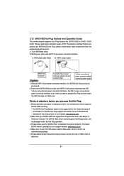
...spec on our support website: www.asrock.com 4. The latest SATA3 driver is de nitely not able to power supply 1. SATA power cable SATA 7-pin connector Caution The SATA 15-pin power connector (Black) connect to SATA3 HDD 1x4-pin conventional power connector (White) connect to support ...Hot Plug and will be processed. 2. Without SATA 15-pin power connector interface, the...
...spec on our support website: www.asrock.com 4. The latest SATA3 driver is de nitely not able to power supply 1. SATA power cable SATA 7-pin connector Caution The SATA 15-pin power connector (Black) connect to SATA3 HDD 1x4-pin conventional power connector (White) connect to support ...Hot Plug and will be processed. 2. Without SATA 15-pin power connector interface, the...

User Manual
Page 32
Step 2 Unplug SATA 15-pin power cable connector (Black) from SATA3 HDD side. connector. How to Hot Unplug a SATA3 HDD: Points of ...Step 2 Connect SATA data cable to end (White) to the SATA3 HDD. Step 4 Connect SATA data cable to the power supply 1x4-pin the motherboard's SATAII / SATA3 cable. How to Hot Plug a SATA3 HDD: Points of attention, before you ...process the Hot Plug, improper procedure will cause the SATA3 HDD damage and data loss. SATA power cable 1x4-pin power connector (White) Step 3 Connect SATA 15-pin power cable connector (Black) end to SATA3 HDD.
Step 2 Unplug SATA 15-pin power cable connector (Black) from SATA3 HDD side. connector. How to Hot Unplug a SATA3 HDD: Points of ...Step 2 Connect SATA data cable to end (White) to the SATA3 HDD. Step 4 Connect SATA data cable to the power supply 1x4-pin the motherboard's SATAII / SATA3 cable. How to Hot Plug a SATA3 HDD: Points of attention, before you ...process the Hot Plug, improper procedure will cause the SATA3 HDD damage and data loss. SATA power cable 1x4-pin power connector (White) Step 3 Connect SATA 15-pin power cable connector (Black) end to SATA3 HDD.

User Manual
Page 44
Use this function may reduce CPU voltage and memory frequency, and lead to system stability or compatibility issue with some memory modules or power supplies. If you enable the item "Core C6 Mode". The default value is [Disabled]. The default value is [Enabled]. Please set to [Enabled], a VMM (Virtual Machine ...
Use this function may reduce CPU voltage and memory frequency, and lead to system stability or compatibility issue with some memory modules or power supplies. If you enable the item "Core C6 Mode". The default value is [Disabled]. The default value is [Enabled]. Please set to [Enabled], a VMM (Virtual Machine ...
Quick Installation Guide
Page 8
... FCC, CE, WHQL - English 8 ASRock A75M-ITX Motherboard ASRock SmartView (see CAUTION 13) - Hybrid Booster: - Chassis Temperature Sensing - ASRock On/Off Play Technology (see CAUTION 10) - ASRock XFast USB (see CAUTION 12) -...asrock.com WARNING Please realize that there is a certain risk involved with overclocking, including adjusting the setting in the BIOS, applying Untied Overclocking Technology, or using the third-party overclocking tools. CPU/Chassis Quiet Fan - Voltage Monitoring: +12V, +5V, +3.3V, Vcore OS - ErP/EuP Ready (ErP/EuP ready power supply...
... FCC, CE, WHQL - English 8 ASRock A75M-ITX Motherboard ASRock SmartView (see CAUTION 13) - Hybrid Booster: - Chassis Temperature Sensing - ASRock On/Off Play Technology (see CAUTION 10) - ASRock XFast USB (see CAUTION 12) -...asrock.com WARNING Please realize that there is a certain risk involved with overclocking, including adjusting the setting in the BIOS, applying Untied Overclocking Technology, or using the third-party overclocking tools. CPU/Chassis Quiet Fan - Voltage Monitoring: +12V, +5V, +3.3V, Vcore OS - ErP/EuP Ready (ErP/EuP ready power supply...

Quick Installation Guide
Page 11
To meet EuP standard, please disable ASRock On/Off Play Technology first. 11 ASRock A75M-ITX Motherboard English To meet EuP standard, an EuP ready motherboard and an EuP ready power supply are required. According to EuP, the total AC power of 5v standby power efficiency is higher than 50% under 1.00W in off mode condition...
To meet EuP standard, please disable ASRock On/Off Play Technology first. 11 ASRock A75M-ITX Motherboard English To meet EuP standard, an EuP ready motherboard and an EuP ready power supply are required. According to EuP, the total AC power of 5v standby power efficiency is higher than 50% under 1.00W in off mode condition...

Quick Installation Guide
Page 12
... not touch the ICs. 4. Also remember to the chassis, please do so may damage the motherboard. 12 ASRock A75M-ITX Motherboard English Before you install or remove any component, place it . Unplug the power cord from the power supply. Installation This is detached from the wall socket before you install the motherboard, study the confi...
... not touch the ICs. 4. Also remember to the chassis, please do so may damage the motherboard. 12 ASRock A75M-ITX Motherboard English Before you install or remove any component, place it . Unplug the power cord from the power supply. Installation This is detached from the wall socket before you install the motherboard, study the confi...

Quick Installation Guide
Page 14
... need to install two identical (the same brand, speed, size and chiptype) memory modules in place and the DIMM is properly seated. 14 ASRock A75M-ITX Motherboard English If you install only one correct orientation. Step 1. Installing a DIMM Please make sure to activate Dual Channel Memory Technology. 2.3 Installation...and DIMM may be damaged. 2. It will operate at both ends fully snap back in the DDR3 DIMM slots to disconnect power supply before adding or removing DIMMs or the system components. Otherwise, it is not allowed to activate the Dual Channel Memory Technology.
... need to install two identical (the same brand, speed, size and chiptype) memory modules in place and the DIMM is properly seated. 14 ASRock A75M-ITX Motherboard English If you install only one correct orientation. Step 1. Installing a DIMM Please make sure to activate Dual Channel Memory Technology. 2.3 Installation...and DIMM may be damaged. 2. It will operate at both ends fully snap back in the DDR3 DIMM slots to disconnect power supply before adding or removing DIMMs or the system components. Otherwise, it is not allowed to activate the Dual Channel Memory Technology.

Quick Installation Guide
Page 15
... start the installation. Step 2. Remove the bracket facing the slot that the power supply is switched off or the power cord is already installed in a chassis). Installing an expansion card Step 1. Keep the screws for later use . Replace the system cover. 15 ASRock A75M-ITX Motherboard English Step 5. Fasten the card to use . Before installing the...
... start the installation. Step 2. Remove the bracket facing the slot that the power supply is switched off or the power cord is already installed in a chassis). Installing an expansion card Step 1. Keep the screws for later use . Replace the system cover. 15 ASRock A75M-ITX Motherboard English Step 5. Fasten the card to use . Before installing the...

Quick Installation Guide
Page 22
.... English 22 ASRock A75M-ITX Motherboard 2.8 Jumpers Setup The illustration shows how jumpers are "Short" when jumper cap is "Open". Jumper Clear CMOS Jumper (CLRCMOS1) (see p.2, No. 23) Setting Default Clear CMOS Description Note: CLRCMOS1 allows you to default setup, please turn off the computer and unplug the power cord from the power supply. After waiting...
.... English 22 ASRock A75M-ITX Motherboard 2.8 Jumpers Setup The illustration shows how jumpers are "Short" when jumper cap is "Open". Jumper Clear CMOS Jumper (CLRCMOS1) (see p.2, No. 23) Setting Default Clear CMOS Description Note: CLRCMOS1 allows you to default setup, please turn off the computer and unplug the power cord from the power supply. After waiting...

Quick Installation Guide
Page 25
... with Pin 1 and Pin 13. 24 13 20-Pin ATX Power Supply Installation 12 ASRock A75M-ITX Motherboard 1 25 English Pin 1-3 Connected 3-Pin Fan Installation (3-pin CPU_FAN2) (see p.2 No. 2) GND +12V CPU_FAN_SPEED ATX Power Connector 24 (24-pin ATXPWR1) 12 (see p.2 No. 3) Please connect an ATX power 13 supply to this connector. 1 Though this motherboard, please connect it...
... with Pin 1 and Pin 13. 24 13 20-Pin ATX Power Supply Installation 12 ASRock A75M-ITX Motherboard 1 25 English Pin 1-3 Connected 3-Pin Fan Installation (3-pin CPU_FAN2) (see p.2 No. 2) GND +12V CPU_FAN_SPEED ATX Power Connector 24 (24-pin ATXPWR1) 12 (see p.2 No. 3) Please connect an ATX power 13 supply to this connector. 1 Though this motherboard, please connect it...

Quick Installation Guide
Page 26
English 26 ASRock A75M-ITX Motherboard This COM1 header supports a serial port module. Please connect the HDMI_SPDIF connector of HDMI VGA card to connect HDMI Digital TV/ projector/LCD devices. HDMI_SPDIF header, providing SPDIF audio output to HDMI VGA card, allows the system to this connector. ATX 12V Power Connector (4-pin ATX12V1) (see p.2 No. 21) Serial port Header (9-pin COM1) (see p.2 No. 5) HDMI_SPDIF Header (2-pin HDMI_SPDIF1) (see p.2 No. 22) 1 GND SPDIFOUT Please connect an ATX 12V power supply to this header.
English 26 ASRock A75M-ITX Motherboard This COM1 header supports a serial port module. Please connect the HDMI_SPDIF connector of HDMI VGA card to connect HDMI Digital TV/ projector/LCD devices. HDMI_SPDIF header, providing SPDIF audio output to HDMI VGA card, allows the system to this connector. ATX 12V Power Connector (4-pin ATX12V1) (see p.2 No. 21) Serial port Header (9-pin COM1) (see p.2 No. 5) HDMI_SPDIF Header (2-pin HDMI_SPDIF1) (see p.2 No. 22) 1 GND SPDIFOUT Please connect an ATX 12V power supply to this header.

