User Manual
Page 3
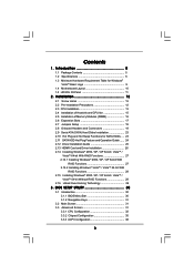
... 32 3.3.2 Chipset Configuration 35 3.3.3 ACPI Configuration 38 3 Installation 12 2.1 Screw Holes 12 2.2 Pre-installation Precautions 12 2.3 CPU Installation 13 2.4 Installation of Heatsink and CPU fan 15 2.5 Installation of Memory Modules (DIMM 16 2.6 Expansion Slots 17 2.7 Jumpers Setup 18 2.8 Onboard Headers and Connectors 19 2.9 Serial ATA (SATA) Hard Disks Installation ...
... 32 3.3.2 Chipset Configuration 35 3.3.3 ACPI Configuration 38 3 Installation 12 2.1 Screw Holes 12 2.2 Pre-installation Precautions 12 2.3 CPU Installation 13 2.4 Installation of Heatsink and CPU fan 15 2.5 Installation of Memory Modules (DIMM 16 2.6 Expansion Slots 17 2.7 Jumpers Setup 18 2.8 Onboard Headers and Connectors 19 2.9 Serial ATA (SATA) Hard Disks Installation ...
User Manual
Page 5
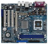
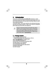
... VGA cards and CPU support lists on ASRock website without notice. Chapter 3 and 4 contain the configuration guide to BIOS setup and information of the motherboard and step-bystep guide to quality and endurance. ASRock website http://www.asrock.com 1.1 Package Contents ASRock 4CoreDX90-VSTA Motherboard (Micro ATX... Panel Shield One COM Port Bracket 5 1. Introduction Thank you for a 3.5-in , 24.4 cm x 20.8 cm) ASRock 4CoreDX90-VSTA Quick Installation Guide ASRock 4CoreDX90-VSTA Support CD One 80-conductor Ultra ATA 66/100/133 IDE Ribbon Cable One Ribbon Cable for purchasing...
... VGA cards and CPU support lists on ASRock website without notice. Chapter 3 and 4 contain the configuration guide to BIOS setup and information of the motherboard and step-bystep guide to quality and endurance. ASRock website http://www.asrock.com 1.1 Package Contents ASRock 4CoreDX90-VSTA Motherboard (Micro ATX... Panel Shield One COM Port Bracket 5 1. Introduction Thank you for a 3.5-in , 24.4 cm x 20.8 cm) ASRock 4CoreDX90-VSTA Quick Installation Guide ASRock 4CoreDX90-VSTA Support CD One 80-conductor Ultra ATA 66/100/133 IDE Ribbon Cable One Ribbon Cable for purchasing...

User Manual
Page 6
Supports Untied Overclocking Technology (see CAUTION 4) - Southbridge: VIA® VT8237A - 2 x DDR DIMM slots - Support DDR400/333/266 - ASRock U-COP (see CAUTION 2) - Boot Failure Guard (B.F.G.) - 3 x PCI slots - 1 x PCI Express x16 slot - 1 x HDMR slot - shared memory... 256MB - 7.1 CH Windows® VistaTM Basic Level HD Audio (ALC883 Audio Codec) - Speed: 10/100 Ethernet - 1.2 Specifications Platform CPU Chipset Memory Hybrid Booster Expansion Slot Graphics Audio LAN Rear Panel I /O - 1 x PS/2 Mouse Port - 1 x PS/2 Keyboard Port - 1 x VGA Port - 1 x...
Supports Untied Overclocking Technology (see CAUTION 4) - Southbridge: VIA® VT8237A - 2 x DDR DIMM slots - Support DDR400/333/266 - ASRock U-COP (see CAUTION 2) - Boot Failure Guard (B.F.G.) - 3 x PCI slots - 1 x PCI Express x16 slot - 1 x HDMR slot - shared memory... 256MB - 7.1 CH Windows® VistaTM Basic Level HD Audio (ALC883 Audio Codec) - Speed: 10/100 Ethernet - 1.2 Specifications Platform CPU Chipset Memory Hybrid Booster Expansion Slot Graphics Audio LAN Rear Panel I /O - 1 x PS/2 Mouse Port - 1 x PS/2 Keyboard Port - 1 x VGA Port - 1 x...

User Manual
Page 7
...Up Events - It should be done at your system. Supports jumperfree - Drivers, Utilities, AntiVirus Software (Trial Version) - CPU Fan Tachometer - CPU Quiet Fan - SMBIOS 2.3.1 Support - We are not responsible for possible damage caused by overclocking. 7 Supports "Plug and ... - 2 x ATA133 IDE connectors (support 4 x IDE devices) - 1 x Floppy connector - 1 x IR header - 1 x COM port header - CPU/Chassis FAN connector - 20 pin ATX power connector - 4 pin 12V power connector - CD in the BIOS, applying Untied Overclocking Technology, or using the thirdparty overclocking...
...Up Events - It should be done at your system. Supports jumperfree - Drivers, Utilities, AntiVirus Software (Trial Version) - CPU Fan Tachometer - CPU Quiet Fan - SMBIOS 2.3.1 Support - We are not responsible for possible damage caused by overclocking. 7 Supports "Plug and ... - 2 x ATA133 IDE connectors (support 4 x IDE devices) - 1 x Floppy connector - 1 x IR header - 1 x COM port header - CPU/Chassis FAN connector - 20 pin ATX power connector - 4 pin 12V power connector - CD in the BIOS, applying Untied Overclocking Technology, or using the thirdparty overclocking...
User Manual
Page 8
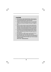
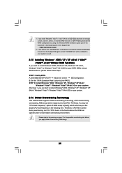
...-bit / XP SP1 or SP2 / 2000 SP4. 7. CAUTION! 1. While CPU overheat is not recommended to spray thermal grease between the CPU and the heatsink when you resume the system, please check if the CPU fan on page 11 for details. 3. Although this motherboard supports 2-channel, 4-...channel, 6-channel, and 8-channel modes. ASRock website http://www.asrock.com 8 Microsoft® Windows&#...
...-bit / XP SP1 or SP2 / 2000 SP4. 7. CAUTION! 1. While CPU overheat is not recommended to spray thermal grease between the CPU and the heatsink when you resume the system, please check if the CPU fan on page 11 for details. 3. Although this motherboard supports 2-channel, 4-...channel, 6-channel, and 8-channel modes. ASRock website http://www.asrock.com 8 Microsoft® Windows&#...
User Manual
Page 9
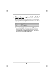
... logo, please adjust the shared memory size of onboard VGA to submit Windows® VistaTM Basic logo, please follow below table for minimum hardware requirement. CPU Memory VGA Celeron D 326 512MB Single Channel* DX9.0 with WDDM Driver * If you use onboard VGA with total system memory size above 512MB and plan...
... logo, please adjust the shared memory size of onboard VGA to submit Windows® VistaTM Basic logo, please follow below table for minimum hardware requirement. CPU Memory VGA Celeron D 326 512MB Single Channel* DX9.0 with WDDM Driver * If you use onboard VGA with total system memory size above 512MB and plan...

User Manual
Page 10
... Chipset PCI EXPRESS IDE1 9 Super I/O 24 23 22 21 LAN PHY 4Mb BIOS Audio CODEC CD1 1 HD_AUDIO1 7.1 CH HD PCIE1 PCI1 4CoreDX90-VSTA PCI2 USB2.0 PCI3 HDMR1 USB4_5 1 USB6_7 1 VIA VT8237A FLOPPY1 CMOS Battery CLRCMOS1 SPEAKER1 1 PANEL 1 PLED PWRBTN 1 HDLED RESET SATA1 SATA2...(ATXPWR1) 17 Clear CMOS Jumper (CLRCMOS1) 4 Chassis Fan Connector (CHA_FAN1) 18 Floppy Connector (FLOPPY1) 5 North Bridge Controller 19 HDMR Slot (HDMR1) 6 775-Pin CPU Socket 20 Front Panel Audio Header (HD_AUDIO1) 7 2 x 184-pin DDR DIMM Slots (DDR1, DDR2; Blue) 21 3 x PCI Slots (PCI1- 3) 8 Secondary...
... Chipset PCI EXPRESS IDE1 9 Super I/O 24 23 22 21 LAN PHY 4Mb BIOS Audio CODEC CD1 1 HD_AUDIO1 7.1 CH HD PCIE1 PCI1 4CoreDX90-VSTA PCI2 USB2.0 PCI3 HDMR1 USB4_5 1 USB6_7 1 VIA VT8237A FLOPPY1 CMOS Battery CLRCMOS1 SPEAKER1 1 PANEL 1 PLED PWRBTN 1 HDLED RESET SATA1 SATA2...(ATXPWR1) 17 Clear CMOS Jumper (CLRCMOS1) 4 Chassis Fan Connector (CHA_FAN1) 18 Floppy Connector (FLOPPY1) 5 North Bridge Controller 19 HDMR Slot (HDMR1) 6 775-Pin CPU Socket 20 Front Panel Audio Header (HD_AUDIO1) 7 2 x 184-pin DDR DIMM Slots (DDR1, DDR2; Blue) 21 3 x PCI Slots (PCI1- 3) 8 Secondary...

User Manual
Page 13
...lever to fully open position at approximately 100 degrees. Insert the 775-LAND CPU: Step 2-1. Orient the CPU with black lines. Step 1-3. Pin1 orientation key notch orientation key notch Pin1 alignment key alignment key 775-LAND CPU 775-Pin Socket 13 black line black line Locate Pin1 and the two ...hook to clear retention tab. Open the socket: Step 1-1. Rotate the load plate to fully open position at approximately 135 degrees. Otherwise, the CPU will be seriously damaged. Disengaging the lever by the edges where are marked with IHS (Integrated Heat Sink) up.
...lever to fully open position at approximately 100 degrees. Insert the 775-LAND CPU: Step 2-1. Orient the CPU with black lines. Step 1-3. Pin1 orientation key notch orientation key notch Pin1 alignment key alignment key 775-LAND CPU 775-Pin Socket 13 black line black line Locate Pin1 and the two ...hook to clear retention tab. Open the socket: Step 1-1. Rotate the load plate to fully open position at approximately 135 degrees. Otherwise, the CPU will be seriously damaged. Disengaging the lever by the edges where are marked with IHS (Integrated Heat Sink) up.

User Manual
Page 14
... within the socket and properly mated to handle and avoid kicking off the PnP cap. 2. Close the socket: Step 4-1. Step 4-2. Step 2-4. Step 4. Verify that the CPU is recommended to use the cap tab to the orient keys. Step 4-3. Remove PnP Cap (Pick and Place Cap): Use your left hand index finger..., please ensure to assist in removal. 1. Step 3. While pressing down lightly on center of PnP cap to match the two orientation key notches of the CPU with load plate tab under retention tab of the socket.
... within the socket and properly mated to handle and avoid kicking off the PnP cap. 2. Close the socket: Step 4-1. Step 4-2. Step 2-4. Step 4. Verify that the CPU is recommended to use the cap tab to the orient keys. Step 4-3. Remove PnP Cap (Pick and Place Cap): Use your left hand index finger..., please ensure to assist in removal. 1. Step 3. While pressing down lightly on center of PnP cap to match the two orientation key notches of the CPU with load plate tab under retention tab of the socket.

User Manual
Page 15
...Before you installed the heatsink, you press down on the motherboard. Then connect the CPU fan to install and lock. If you need to spray thermal interface material between the CPU and the heatsink to the CPU fan connector on the motherboard (CPU_FAN1, see page 10, No. 4). Step ...5. Step 1. Align fasteners with remaining fasteners. Ensure that supports Intel 775-LAND CPU. For proper installation, please kindly refer to ensure cable does not interfere with the CPU fan connector on the socket surface. Rotate the fastener clockwise, then press down the fasteners without ...
...Before you installed the heatsink, you press down on the motherboard. Then connect the CPU fan to install and lock. If you need to spray thermal interface material between the CPU and the heatsink to the CPU fan connector on the motherboard (CPU_FAN1, see page 10, No. 4). Step ...5. Step 1. Align fasteners with remaining fasteners. Ensure that supports Intel 775-LAND CPU. For proper installation, please kindly refer to ensure cable does not interfere with the CPU fan connector on the socket surface. Rotate the fastener clockwise, then press down the fasteners without ...

User Manual
Page 21
...motherboard, please connect it to MIC2_L. Though this header. Pin 1-3 Connected 3-Pin Fan Installation 21 If you plan to connect the 3-Pin CPU fan to the CPU fan connector on the lower right hand taskbar to the ground pin. Connect Mic_IN (MIC) to the front panel audio header as below:...+12V CHA_FAN_SPEED Please connect the chassis fan cable to this connector and match the black wire to this motherboard provides 4-Pin CPU fan (Quiet Fan) support, the 3-Pin CPU fan still can work successfully even without the fan speed control function. If you use AC'97 audio panel, please install ...
...motherboard, please connect it to MIC2_L. Though this header. Pin 1-3 Connected 3-Pin Fan Installation 21 If you plan to connect the 3-Pin CPU fan to the CPU fan connector on the lower right hand taskbar to the ground pin. Connect Mic_IN (MIC) to the front panel audio header as below:...+12V CHA_FAN_SPEED Please connect the chassis fan cable to this connector and match the black wire to this motherboard provides 4-Pin CPU fan (Quiet Fan) support, the 3-Pin CPU fan still can work successfully even without the fan speed control function. If you use AC'97 audio panel, please install ...
User Manual
Page 29
... frequency in the Support CD: .. \ RAID Installation Guide 2. Therefore, CPU FSB is untied during overclocking, FSB enjoys better margin due to manage (create, convert, delete, or rebuild) RAID functions on your system as well. 2.15 ... Windows® 2000 / Windows® XP / Windows® XP 64-bit / Windows® VistaTM / Windows® VistaTM 64-bit OS on SATA HDDs,please set "CPU Host Frequency" option of the document in the following path in the following item. If you install Windows® VistaTM / VistaTM 64-bit on IDE...
... frequency in the Support CD: .. \ RAID Installation Guide 2. Therefore, CPU FSB is untied during overclocking, FSB enjoys better margin due to manage (create, convert, delete, or rebuild) RAID functions on your system as well. 2.15 ... Windows® 2000 / Windows® XP / Windows® XP 64-bit / Windows® VistaTM / Windows® VistaTM 64-bit OS on SATA HDDs,please set "CPU Host Frequency" option of the document in the following path in the following item. If you install Windows® VistaTM / VistaTM 64-bit on IDE...

User Manual
Page 31
... H/W Monitor Boot Security Exit System Overview System Time System Date [17:00:09] [Mon 03/12/2007] BIOS Version : 4CoreDX90-VSTA BIOS P1.00 Processor Type : Intel (R) CPU 3.40 GHz (64bit supported) Processor Speed : 3400MHz Microcode Update : F65/7 Cache Size : 4096KB Total Memory DRD 1 DDR ... for the function description of each navigation key. 3.1.2 Navigation Keys Please check the following items: CPU Configuration, Chipset Configuration, ACPI Configuration, IDE Configuration, PCIPnP Configuration, Floppy Configuration, SuperIO Configuration, and USB Configuration. 31
... H/W Monitor Boot Security Exit System Overview System Time System Date [17:00:09] [Mon 03/12/2007] BIOS Version : 4CoreDX90-VSTA BIOS P1.00 Processor Type : Intel (R) CPU 3.40 GHz (64bit supported) Processor Speed : 3400MHz Microcode Update : F65/7 Cache Size : 4096KB Total Memory DRD 1 DDR ... for the function description of each navigation key. 3.1.2 Navigation Keys Please check the following items: CPU Configuration, Chipset Configuration, ACPI Configuration, IDE Configuration, PCIPnP Configuration, Floppy Configuration, SuperIO Configuration, and USB Configuration. 31

User Manual
Page 32
... Enable or disable the feature of this to select PCIE clock operation mode. mode]. Configuration options: [Sync. mode]. 32 The actual CPU host frequency will show in the following item. Spread Spectrum Select [Auto] for the spread spectrum feature. BIOS SETUP UTILITY Main Advanced ... the system to malfunction. mode] Ratio Status Unlocked (Max: 17, Min: 12) Ratio Actual Value 17 Enhanced Halt State Max CPUID Value Limit CPU Throttling No-Excute Memory Protection Intel (R) SpeedStep (tm) tech. [Disabled] [Disabled] [Enabled] [Disabled] [Auto] Select how to Sub Screen...
... Enable or disable the feature of this to select PCIE clock operation mode. mode]. Configuration options: [Sync. mode]. 32 The actual CPU host frequency will show in the following item. Spread Spectrum Select [Auto] for the spread spectrum feature. BIOS SETUP UTILITY Main Advanced ... the system to malfunction. mode] Ratio Status Unlocked (Max: 17, Min: 12) Ratio Actual Value 17 Enhanced Halt State Max CPUID Value Limit CPU Throttling No-Excute Memory Protection Intel (R) SpeedStep (tm) tech. [Disabled] [Disabled] [Enabled] [Disabled] [Auto] Select how to Sub Screen...

User Manual
Page 33
... Intel Architecture. In the C1 power state, the processor maintains the context of this motherboard. This should be hidden if the current CPU does not support CPU Thermal Throttling. This option will be enabled in advance. An IA-32 processor with "No Execute (NX) Memory Protection" can utilize.... in order to execute code. This option will find an item Ratio CMOS Setting appears to allow you will be hidden if the current CPU does not support No-Excute Memory Protection. No-Excute Memory Protection No-Execution (NX) Memory Protection Technology is set to [Enabled], a VMM...
... Intel Architecture. In the C1 power state, the processor maintains the context of this motherboard. This should be hidden if the current CPU does not support CPU Thermal Throttling. This option will be enabled in advance. An IA-32 processor with "No Execute (NX) Memory Protection" can utilize.... in order to execute code. This option will find an item Ratio CMOS Setting appears to allow you will be hidden if the current CPU does not support No-Excute Memory Protection. No-Excute Memory Protection No-Execution (NX) Memory Protection Technology is set to [Enabled], a VMM...

User Manual
Page 34
... install Windows® VistaTM and want to system stability or compatibility issue with some power supplies. If you need to set this function may reduce CPU voltage and lead to enable this function, please set this function. Please note that enabling this item to [Enabled]. Intel (R) SpeedStep(tm) tech. Windows®..." to enable this item to [Disable] if above issue occurs. 34 Configuration options: [Auto], [Enabled] and [Disabled]. This item will be hidden if the current CPU does not support Intel (R) SpeedStep(tm) tech.. Intel (R) SpeedStep(tm) tech. is [Auto].
... install Windows® VistaTM and want to system stability or compatibility issue with some power supplies. If you need to set this function may reduce CPU voltage and lead to enable this function, please set this function. Please note that enabling this item to [Enabled]. Intel (R) SpeedStep(tm) tech. Windows®..." to enable this item to [Disable] if above issue occurs. 34 Configuration options: [Auto], [Enabled] and [Disabled]. This item will be hidden if the current CPU does not support Intel (R) SpeedStep(tm) tech.. Intel (R) SpeedStep(tm) tech. is [Auto].

User Manual
Page 44
... monitor the status of the hardware on your system, including the parameters of CPU fan. You are allowed to enable this function only when you to identify the temperature of the CPU temperature, motherboard temperature, CPU fan speed, chassis fan speed, and the critical voltage. The default value ... Hardware Health Event Monitoring Screen In this section, it allows you set this option as [Enabled], you will find the item "Target CPU Temperature ( C)" appear to allow you adjusting it. BIOS SETUP UTILITY Main Advanced H/W Monitor Boot Security Exit Hardware Health Event Monitoring...
... monitor the status of the hardware on your system, including the parameters of CPU fan. You are allowed to enable this function only when you to identify the temperature of the CPU temperature, motherboard temperature, CPU fan speed, chassis fan speed, and the critical voltage. The default value ... Hardware Health Event Monitoring Screen In this section, it allows you set this option as [Enabled], you will find the item "Target CPU Temperature ( C)" appear to allow you adjusting it. BIOS SETUP UTILITY Main Advanced H/W Monitor Boot Security Exit Hardware Health Event Monitoring...

Quick Installation Guide
Page 2
... Port Connector (COM1) 12 Secondary Serial ATA Connector (SATA2) 26 Infrared Module Header (IR1) 13 Primary Serial ATA Connector (SATA1) 27 CPU Fan Connector (CPU_FAN1) 14 System Panel Header (PANEL1) 2 ASRock 4CoreDX90-VSTA Motherboard Motherboard Layout English 1 PS2_USB_PWR1 Jumper 15 South Bridge Controller 2 ATX 12V Connector (ATX12V1) 16 Chassis Speaker Header (SPEAKER 1) 3 ATX Power...
... Port Connector (COM1) 12 Secondary Serial ATA Connector (SATA2) 26 Infrared Module Header (IR1) 13 Primary Serial ATA Connector (SATA1) 27 CPU Fan Connector (CPU_FAN1) 14 System Panel Header (PANEL1) 2 ASRock 4CoreDX90-VSTA Motherboard Motherboard Layout English 1 PS2_USB_PWR1 Jumper 15 South Bridge Controller 2 ATX 12V Connector (ATX12V1) 16 Chassis Speaker Header (SPEAKER 1) 3 ATX Power...

Quick Installation Guide
Page 4
... VGA cards and CPU support lists on ASRock website without notice. 1. It delivers excellent performance with robust design conforming to ASRock's commitment to change without further notice. More detailed information of the motherboard and step-bystep installation guide. Introduction Thank you for a 3.5-in , 24.4 cm x 20.8 cm) ASRock 4CoreDX90-VSTA Quick Installation Guide ASRock 4CoreDX90-VSTA Support CD One...
... VGA cards and CPU support lists on ASRock website without notice. 1. It delivers excellent performance with robust design conforming to ASRock's commitment to change without further notice. More detailed information of the motherboard and step-bystep installation guide. Introduction Thank you for a 3.5-in , 24.4 cm x 20.8 cm) ASRock 4CoreDX90-VSTA Quick Installation Guide ASRock 4CoreDX90-VSTA Support CD One...

Quick Installation Guide
Page 5
... VT6103 - Speed: 10/100 Ethernet - Micro ATX Form Factor: 9.6-in x 8.2-in /Front Speaker/Microphone (see CAUTION 5) English 5 ASRock 4CoreDX90-VSTA Motherboard Southbridge: VIA® VT8237A - 2 x DDR DIMM slots - Max. capacity: 2GB - Boot Failure Guard (B.F.G.) - 3 x PCI...CAUTION 1) - Northbridge: VIA® P4M900 - ASRock U-COP (see CAUTION 3) - Supports EM64T CPU - Support DDR400/333/266 - Pixel Shader 2.0, DirectX 9.0 - CPU Frequency Stepless Control (see CAUTION 4) - 1.2 Specifications Platform CPU Chipset Memory Hybrid Booster Expansion Slot Graphics Audio ...
... VT6103 - Speed: 10/100 Ethernet - Micro ATX Form Factor: 9.6-in x 8.2-in /Front Speaker/Microphone (see CAUTION 5) English 5 ASRock 4CoreDX90-VSTA Motherboard Southbridge: VIA® VT8237A - 2 x DDR DIMM slots - Max. capacity: 2GB - Boot Failure Guard (B.F.G.) - 3 x PCI...CAUTION 1) - Northbridge: VIA® P4M900 - ASRock U-COP (see CAUTION 3) - Supports EM64T CPU - Support DDR400/333/266 - Pixel Shader 2.0, DirectX 9.0 - CPU Frequency Stepless Control (see CAUTION 4) - 1.2 Specifications Platform CPU Chipset Memory Hybrid Booster Expansion Slot Graphics Audio ...


