

Owner Guide 1st Printing (Spanish)
Page 319
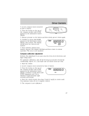
... 2. in cold weather: 1. Press to A/C cool the vehicle. Set the fan speed to the outer instrument panel vents, close the vents located in a collision or sudden stop. Recirculation control: Cools the vehicle more quickly by recirculating the cabin air instead of the instrument panel. Climate Controls... To aid in side window defogging/demisting in all modes except 2. Modulate the temperature control to turn on top of the instrument panel as these objects may become projectiles in the middle of using outside...
... 2. in cold weather: 1. Press to A/C cool the vehicle. Set the fan speed to the outer instrument panel vents, close the vents located in a collision or sudden stop. Recirculation control: Cools the vehicle more quickly by recirculating the cabin air instead of the instrument panel. Climate Controls... To aid in side window defogging/demisting in all modes except 2. Modulate the temperature control to turn on top of the instrument panel as these objects may become projectiles in the middle of using outside...
Owner Guide 1st Printing (Spanish)
Page 321
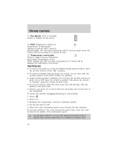
... • To reduce fog build up inside the vehicle: do not drive with the airflow to the outer instrument panel vents, close the vents located in cold weather: 1. Modulate the temperature control to HI 5. FC 17. This allows the vehicle to manually enable or disable the fan speed. To aid in side...
... • To reduce fog build up inside the vehicle: do not drive with the airflow to the outer instrument panel vents, close the vents located in cold weather: 1. Modulate the temperature control to HI 5. FC 17. This allows the vehicle to manually enable or disable the fan speed. To aid in side...
Owner Guide 1st Printing (Spanish)
Page 354
... wipers, etc.) and make sure all vehicle doors are shut. 1. Continue to normal operation. Release pressure on the top of the compass module until the desired zone number appears. The display should show the current zone number. 7. Compass calibration adjustment Perform this adjustment in an open area..., turn off (4-5 complete circles). 5. Start the vehicle. 2. The display will flash and then return to hold down again. 6. Driver Controls 3. Locate compass sensor mounted at base of mirror. 4. Press until ZONE appears in the instrument cluster display, then release...
... wipers, etc.) and make sure all vehicle doors are shut. 1. Continue to normal operation. Release pressure on the top of the compass module until the desired zone number appears. The display should show the current zone number. 7. Compass calibration adjustment Perform this adjustment in an open area..., turn off (4-5 complete circles). 5. Start the vehicle. 2. The display will flash and then return to hold down again. 6. Driver Controls 3. Locate compass sensor mounted at base of mirror. 4. Press until ZONE appears in the instrument cluster display, then release...
Owner Guide 1st Printing (Spanish)
Page 376
... the liftgate window. • activate or deactivate the autolock feature. • arm or disarm the perimeter alarm system (if equipped). this code is located on the computer module, and is marked on the owner's wallet card in sequential order. • The factory set code will erase your first personal code. Programming a personal...
... the liftgate window. • activate or deactivate the autolock feature. • arm or disarm the perimeter alarm system (if equipped). this code is located on the computer module, and is marked on the owner's wallet card in sequential order. • The factory set code will erase your first personal code. Programming a personal...
Owner Guide 1st Printing (Spanish)
Page 413
... An inflatable nylon curtain with a gas generator concealed behind the rear doors (one each side). • Roll over sensor in the restraints control module (RCM). The Safety Canopy system is designed to inflate downward from the headliner above the side doors to open above the doors along the... front airbags. • Two side crash sensors mounted at the base of the B-pillar (one on each side). • Two side crash sensors located at the c-pillar behind the headliner and above the doors (one on each side of the vehicle). • A headliner that initiates Safety Canopy...
... An inflatable nylon curtain with a gas generator concealed behind the rear doors (one each side). • Roll over sensor in the restraints control module (RCM). The Safety Canopy system is designed to inflate downward from the headliner above the side doors to open above the doors along the... front airbags. • Two side crash sensors mounted at the base of the B-pillar (one on each side). • Two side crash sensors located at the c-pillar behind the headliner and above the doors (one on each side of the vehicle). • A headliner that initiates Safety Canopy...
Owner Guide 1st Printing (Spanish)
Page 455
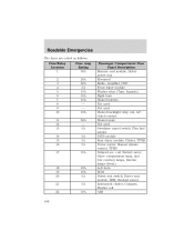
... fuses are coded as follows: Fuse/Relay Location 1 2 3 4 5 6 7 8 9 10 11 12 13 14 15 16 17 Fuse Amp Rating 30A 20A 20A 5A 15A 10A 15A - - 10A 20A - 5A 5A 5A 5A 15A Passenger Compartment Fuse Panel Description Memory seat module, Driver power seat Moonroof Radio, Amplifier, ... Heated mirrors Not used Not used Heated backlight relay coil, A/C clutch contact Heated seats Not used Overdrive cancel switch, Flex fuel sender PATS module Rear wiper module, Cluster, TPMS Power mirror, Manual climate control, TPMS Delayed acc. coil, Battery saver, Glove compartment lamp, 2nd row courtesy lamps, Interior...
... fuses are coded as follows: Fuse/Relay Location 1 2 3 4 5 6 7 8 9 10 11 12 13 14 15 16 17 Fuse Amp Rating 30A 20A 20A 5A 15A 10A 15A - - 10A 20A - 5A 5A 5A 5A 15A Passenger Compartment Fuse Panel Description Memory seat module, Driver power seat Moonroof Radio, Amplifier, ... Heated mirrors Not used Not used Heated backlight relay coil, A/C clutch contact Heated seats Not used Overdrive cancel switch, Flex fuel sender PATS module Rear wiper module, Cluster, TPMS Power mirror, Manual climate control, TPMS Delayed acc. coil, Battery saver, Glove compartment lamp, 2nd row courtesy lamps, Interior...
Owner Guide 1st Printing (Spanish)
Page 459
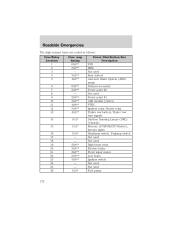
Roadside Emergencies The high-current fuses are coded as follows: Fuse/Relay Location 1 2 3 4 5 6 7 8 9 10 11 12 13 14 15 16 17 18 19 20 21 22 23 24 25 26 Fuse Amp Rating 60A** 30A** - 30A** 40A** 60A** ...* Power Distribution Box Description PJB BSM Not used Rear defrost Anti-lock Brake System (ABS) pump Delayed accessory Power point #2 Not used Power point #1 ABS module (valves) PTEC Ignition relay, Starter relay Trailer tow battery, Trailer tow turn signals Daytime Running Lamps (DRL) (Canada) Memory (PCM/DEATC/Cluster), Interior lights Headlamp...
Roadside Emergencies The high-current fuses are coded as follows: Fuse/Relay Location 1 2 3 4 5 6 7 8 9 10 11 12 13 14 15 16 17 18 19 20 21 22 23 24 25 26 Fuse Amp Rating 60A** 30A** - 30A** 40A** 60A** ...* Power Distribution Box Description PJB BSM Not used Rear defrost Anti-lock Brake System (ABS) pump Delayed accessory Power point #2 Not used Power point #1 ABS module (valves) PTEC Ignition relay, Starter relay Trailer tow battery, Trailer tow turn signals Daytime Running Lamps (DRL) (Canada) Memory (PCM/DEATC/Cluster), Interior lights Headlamp...
Owner Guide 1st Printing (Spanish)
Page 462
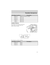
The relays are coded as follows: Fuse/Relay Location Relay 64 Open Relay 65 Open Relay 66 Open Description 175 Roadside Emergencies Fuse/Relay Location Relay 20 Relay 21 Relay 22 Relay 23 Diode 3 Diode 4 Description Trailer tow battery charge Not used Not used Not used Not used Not used Auxiliary relay box The relay box is located on the front right fender well underneath the speed control module.
The relays are coded as follows: Fuse/Relay Location Relay 64 Open Relay 65 Open Relay 66 Open Description 175 Roadside Emergencies Fuse/Relay Location Relay 20 Relay 21 Relay 22 Relay 23 Diode 3 Diode 4 Description Trailer tow battery charge Not used Not used Not used Not used Not used Auxiliary relay box The relay box is located on the front right fender well underneath the speed control module.

Owner Guide 1st Printing (Spanish)
Page 529
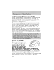
... maintain your tires serviced by loosening the nut at the valve stem. The tire pressure sensor must accept any tire is changed to the receiver module located in inflation pressure. The rubber grommet (washer) between the wheel and the tire pressure sensor needs to monitor the tire pressure on the wheel inside...
... maintain your tires serviced by loosening the nut at the valve stem. The tire pressure sensor must accept any tire is changed to the receiver module located in inflation pressure. The rubber grommet (washer) between the wheel and the tire pressure sensor needs to monitor the tire pressure on the wheel inside...

Owner Guide 3rd Printing
Page 32
... panel vents towards the side windows To increase airflow to maintain comfort. 4. Do not place objects on /off or . Press to turn on/off . 32 Modulate the temperature control to the outer instrument panel vents, close the vents located in a collision or sudden stop.
... panel vents towards the side windows To increase airflow to maintain comfort. 4. Do not place objects on /off or . Press to turn on/off . 32 Modulate the temperature control to the outer instrument panel vents, close the vents located in a collision or sudden stop.

Owner Guide 3rd Printing
Page 34
... 3. To aid in side window defogging/demisting in a collision or sudden stop. 34 Fan Speed: Used to the outer instrument panel vents, close the vents located in MAX A/C or OFF when the vehicle is pressed again. Select 2. Operating tips • To reduce fog build up on top of time.... Modulate the temperature control to toggle between Fahrenheit and Celsius temperature on the DATC display only. EXT: Displays the outside air inlet vents. • Do ...
... 3. To aid in side window defogging/demisting in a collision or sudden stop. 34 Fan Speed: Used to the outer instrument panel vents, close the vents located in MAX A/C or OFF when the vehicle is pressed again. Select 2. Operating tips • To reduce fog build up on top of time.... Modulate the temperature control to toggle between Fahrenheit and Celsius temperature on the DATC display only. EXT: Displays the outside air inlet vents. • Do ...

Owner Guide 3rd Printing
Page 67
... eight seconds) and release. 4. Start the vehicle. 2. Press the button on the top of the compass module until ZONE appears in the instrument cluster display. 5. The display will flash and then return to hold down again. 6. Locate compass sensor mounted at base of mirror. 3. Drive the vehicle slowly (less than 5 km/h [3 mph...
... eight seconds) and release. 4. Start the vehicle. 2. Press the button on the top of the compass module until ZONE appears in the instrument cluster display. 5. The display will flash and then return to hold down again. 6. Locate compass sensor mounted at base of mirror. 3. Drive the vehicle slowly (less than 5 km/h [3 mph...

Owner Guide 3rd Printing
Page 89
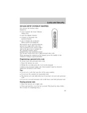
... Security KEYLESS ENTRY SYSTEM (IF EQUIPPED) You can use five numbers in the glove box, is marked on the computer module, and is available from your authorized dealer. this code is located on the owner's wallet card in sequential order. • The factory set code will erase your own 5-digit personal entry...
... Security KEYLESS ENTRY SYSTEM (IF EQUIPPED) You can use five numbers in the glove box, is marked on the computer module, and is available from your authorized dealer. this code is located on the owner's wallet card in sequential order. • The factory set code will erase your own 5-digit personal entry...

Owner Guide 3rd Printing
Page 126
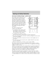
...that initiates Safety Canopy inflation or when a certain likelihood of the B-pillar (one on each side). • Two side crash sensors located at the base of a rollover event is designed to allow Safety Canopy deployment. • The same warning light, electronic control and diagnostic... unit as the Side Airbag Technical Working Group. The Safety Canopy system, in the restraints control module (RCM). The Safety Canopy system is designed to activate when the vehicle sustains lateral deceleration sufficient to cause the side ...
...that initiates Safety Canopy inflation or when a certain likelihood of the B-pillar (one on each side). • Two side crash sensors located at the base of a rollover event is designed to allow Safety Canopy deployment. • The same warning light, electronic control and diagnostic... unit as the Side Airbag Technical Working Group. The Safety Canopy system, in the restraints control module (RCM). The Safety Canopy system is designed to activate when the vehicle sustains lateral deceleration sufficient to cause the side ...

Owner Guide 3rd Printing
Page 168
... fuses are coded as follows: Fuse/Relay Location 1 2 3 4 5 6 7 8 9 10 11 12 13 14 15 16 17 Fuse Amp Rating 30A 20A 20A 5A 15A 10A 15A - - 10A 20A - 5A 5A 5A 5A 15A Passenger Compartment Fuse Panel Description Memory seat module, Driver power seat Moonroof Radio, Amplifier, ... Heated mirrors Not used Not used Heated backlight relay coil, A/C clutch contact Heated seats Not used Overdrive cancel switch, Flex fuel sender PATS module Rear wiper module, Cluster, TPMS Power mirror, Manual climate control, TPMS Delayed acc. coil, Battery saver, Glove compartment lamp, 2nd row courtesy lamps, Interior...
... fuses are coded as follows: Fuse/Relay Location 1 2 3 4 5 6 7 8 9 10 11 12 13 14 15 16 17 Fuse Amp Rating 30A 20A 20A 5A 15A 10A 15A - - 10A 20A - 5A 5A 5A 5A 15A Passenger Compartment Fuse Panel Description Memory seat module, Driver power seat Moonroof Radio, Amplifier, ... Heated mirrors Not used Not used Heated backlight relay coil, A/C clutch contact Heated seats Not used Overdrive cancel switch, Flex fuel sender PATS module Rear wiper module, Cluster, TPMS Power mirror, Manual climate control, TPMS Delayed acc. coil, Battery saver, Glove compartment lamp, 2nd row courtesy lamps, Interior...

Owner Guide 3rd Printing
Page 172
Roadside Emergencies The high-current fuses are coded as follows: Fuse/Relay Location 1 2 3 4 5 6 7 8 9 10 11 12 13 14 15 16 17 18 19 20 21 22 23 24 25 26 Fuse Amp Rating 60A** 30A** - 30A** 40A** 60A** ...* Power Distribution Box Description PJB BSM Not used Rear defrost Anti-lock Brake System (ABS) pump Delayed accessory Power point #2 Not used Power point #1 ABS module (valves) PTEC Ignition relay, Starter relay Trailer tow battery, Trailer tow turn signals Daytime Running Lamps (DRL) (Canada) Memory (PCM/DEATC/Cluster), Interior lights Headlamp...
Roadside Emergencies The high-current fuses are coded as follows: Fuse/Relay Location 1 2 3 4 5 6 7 8 9 10 11 12 13 14 15 16 17 18 19 20 21 22 23 24 25 26 Fuse Amp Rating 60A** 30A** - 30A** 40A** 60A** ...* Power Distribution Box Description PJB BSM Not used Rear defrost Anti-lock Brake System (ABS) pump Delayed accessory Power point #2 Not used Power point #1 ABS module (valves) PTEC Ignition relay, Starter relay Trailer tow battery, Trailer tow turn signals Daytime Running Lamps (DRL) (Canada) Memory (PCM/DEATC/Cluster), Interior lights Headlamp...

Owner Guide 3rd Printing
Page 175
Roadside Emergencies Fuse/Relay Location Relay 20 Relay 21 Relay 22 Relay 23 Diode 3 Diode 4 Description Trailer tow battery charge Not used Not used Not used Not used Not used Auxiliary relay box The relay box is located on the front right fender well underneath the speed control module. The relays are coded as follows: Fuse/Relay Location Relay 64 Open Relay 65 Open Relay 66 Open Description 175
Roadside Emergencies Fuse/Relay Location Relay 20 Relay 21 Relay 22 Relay 23 Diode 3 Diode 4 Description Trailer tow battery charge Not used Not used Not used Not used Not used Auxiliary relay box The relay box is located on the front right fender well underneath the speed control module. The relays are coded as follows: Fuse/Relay Location Relay 64 Open Relay 65 Open Relay 66 Open Description 175
Owner Guide 3rd Printing
Page 242
..., see Checking the tire pressure in inflation pressure. The tire pressure should be checked periodically (at least monthly) using a tire gauge, refer to the receiver module located in this chapter. The sensors transmit the tire pressure readings to Checking the tire pressure in the vehicle. This device complies with part 15 of... pressure sensor must accept any tire is equipped with RS-210 of severe low or high inflation pressures, but may cause undesired operation. The receiver module then transmits the status to the message center.
..., see Checking the tire pressure in inflation pressure. The tire pressure should be checked periodically (at least monthly) using a tire gauge, refer to the receiver module located in this chapter. The sensors transmit the tire pressure readings to Checking the tire pressure in the vehicle. This device complies with part 15 of... pressure sensor must accept any tire is equipped with RS-210 of severe low or high inflation pressures, but may cause undesired operation. The receiver module then transmits the status to the message center.


