Owner's Manual
Page 49
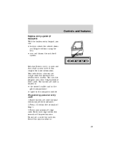
... system. 1•2 3•4 5•6 7•8 9•0 See also Remote entry system and Anti-theft system later in the glove compartment • taped to the computer module Programming personal entry code 1. Enter your own 5-digit personal entry code.
... system. 1•2 3•4 5•6 7•8 9•0 See also Remote entry system and Anti-theft system later in the glove compartment • taped to the computer module Programming personal entry code 1. Enter your own 5-digit personal entry code.
Owner's Manual
Page 50
Enter factory-set code. The system will unlock. Press 3/4 button within five seconds of unlocking driver door. If a second personal code is entered, the module will illuminate. 2. Wait six seconds. Locking doors with the keyless entry system 1. Driver door will unlock and interior lamps will erase the old code in a ...
Enter factory-set code. The system will unlock. Press 3/4 button within five seconds of unlocking driver door. If a second personal code is entered, the module will illuminate. 2. Wait six seconds. Locking doors with the keyless entry system 1. Driver door will unlock and interior lamps will erase the old code in a ...

Owner's Manual
Page 73
... the passenger air bag near the glove compartment. • The electrical system, made up power, and the air bag ignitors. The diagnostic module monitors its own internal circuits and the supplemental air bag electrical system readiness (including the impact sensors), the system wiring, the air bag system... bag back up of a second after air bag sensors detect a severe frontal collision. Gas generators within a fraction of impact sensors, a diagnostic module, and a backup power supply. The air bags inflate within the air bags fill the air bags with a non-toxic, non-flammable gas.
... the passenger air bag near the glove compartment. • The electrical system, made up power, and the air bag ignitors. The diagnostic module monitors its own internal circuits and the supplemental air bag electrical system readiness (including the impact sensors), the system wiring, the air bag system... bag back up of a second after air bag sensors detect a severe frontal collision. Gas generators within a fraction of impact sensors, a diagnostic module, and a backup power supply. The air bags inflate within the air bags fill the air bags with a non-toxic, non-flammable gas.
Owner's Manual
Page 123
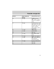
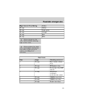
Roadside emergencies Number 26 Fuse Amperage Rating 10 amp Circuits Protected 4R70W overdrive, DRL system, backup lamps, rear defroster relay Underhood lamp, map lights, glove box lamp, overhead lamp, visor lamps, accessory delay, dimmer switch illumination GEM system Audio system Not used Rear blower motor relay Heated rear window DRL module, RH and LH headlamp, instrument cluster Luxury audio system Not used Not used 27 10 amp 28 29 30 31 32 33 7.5 amp 10 amp 7.5 amp 7.5 amp 15 amp 34 35 36 7.5 amp - 123
Roadside emergencies Number 26 Fuse Amperage Rating 10 amp Circuits Protected 4R70W overdrive, DRL system, backup lamps, rear defroster relay Underhood lamp, map lights, glove box lamp, overhead lamp, visor lamps, accessory delay, dimmer switch illumination GEM system Audio system Not used Rear blower motor relay Heated rear window DRL module, RH and LH headlamp, instrument cluster Luxury audio system Not used Not used 27 10 amp 28 29 30 31 32 33 7.5 amp 10 amp 7.5 amp 7.5 amp 15 amp 34 35 36 7.5 amp - 123
Owner's Manual
Page 125
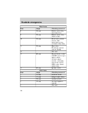
Always replace the cover to the power distribution box before servicing high current fuses. Color Yellow Light green Orange Red Blue Maxi fuses Fuse 1 2 3 4 Amps 30 amp 30 amp 20 amp 20 amp Circuits protected Rear window defrost relay PCM power relay Fuel pump relay, RAP module Headlamps, autolamps, multi-function switch 4WABS pump relay 4WABS main relay Trailer tow relays 5 6 7 30 amp 30 amp 20 amp 125 Roadside emergencies High Current Fuse Rating 20 amp 30 amp 40 amp 50 amp 60 amp Always disconnect the battery before reconnecting the battery or refilling fluid reservoirs.
Always replace the cover to the power distribution box before servicing high current fuses. Color Yellow Light green Orange Red Blue Maxi fuses Fuse 1 2 3 4 Amps 30 amp 30 amp 20 amp 20 amp Circuits protected Rear window defrost relay PCM power relay Fuel pump relay, RAP module Headlamps, autolamps, multi-function switch 4WABS pump relay 4WABS main relay Trailer tow relays 5 6 7 30 amp 30 amp 20 amp 125 Roadside emergencies High Current Fuse Rating 20 amp 30 amp 40 amp 50 amp 60 amp Always disconnect the battery before reconnecting the battery or refilling fluid reservoirs.
Owner's Manual
Page 126
... Battery saver relay, headlamp relay Blower motor relay, blower motor Power seats, power lumbar, door lock/unlock relays, accessory delay relay Horn relay, Powertrain control module (PCM) Not used Hazard flasher, brake ON/OFF switch, cigar lighter, power antenna, power mirrors, autolamps, instrument cluster, GEM, radio, blower motor relay Ignition switch...
... Battery saver relay, headlamp relay Blower motor relay, blower motor Power seats, power lumbar, door lock/unlock relays, accessory delay relay Horn relay, Powertrain control module (PCM) Not used Hazard flasher, brake ON/OFF switch, cigar lighter, power antenna, power mirrors, autolamps, instrument cluster, GEM, radio, blower motor relay Ignition switch...
Owner's Manual
Page 127
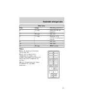
Relays receive signals from components or systems and transfer these signals to activate or deactivate other components or systems. Mercury recommends that relays be replaced by a qualified technician. 6 2 1 5 3 2 1 4 127 Roadside emergencies Mini fuses Fuse 6 7 8 Amps 15 amp 20 amp 15 amp Circuits protected Generator/voltage regulator Not used Foglamp relay, daytime running lamp module Not used Not used HEGO system 9 10 11 20 amp Relays Relays are located in the power distribution box.
Relays receive signals from components or systems and transfer these signals to activate or deactivate other components or systems. Mercury recommends that relays be replaced by a qualified technician. 6 2 1 5 3 2 1 4 127 Roadside emergencies Mini fuses Fuse 6 7 8 Amps 15 amp 20 amp 15 amp Circuits protected Generator/voltage regulator Not used Foglamp relay, daytime running lamp module Not used Not used HEGO system 9 10 11 20 amp Relays Relays are located in the power distribution box.
Warranty Guide 1st Printing
Page 7
... pump, water pump, fuel pump and fuel system (excluding fuel lines and fuel tank), high pressure lines, gaskets and seals, glow plugs, turbocharger, powertrain control module, electronic driver unit, injectors, injection pressure sensor, high pressure oil regulator, exhaust back pressure regulator and sensor, camshaft position sensor, accelerator switch. workmanship for an...
... pump, water pump, fuel pump and fuel system (excluding fuel lines and fuel tank), high pressure lines, gaskets and seals, glow plugs, turbocharger, powertrain control module, electronic driver unit, injectors, injection pressure sensor, high pressure oil regulator, exhaust back pressure regulator and sensor, camshaft position sensor, accelerator switch. workmanship for an...
Warranty Guide 1st Printing
Page 14
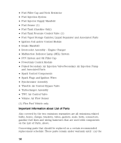
... Tank Pressure Control Valve (1) • Fuel Vapor Storage Canister, Liquid Separator and Associated Parts • Ignition Coil and/or Control Module • Intake Manifold • Intercooler Assembly - Engine Charger • Malfunction Indicator Lamp (MIL) System • PCV System and Oil ...Filler Cap • Powertrain Control Module • Pulsed Secondary Air Injection Valve/Secondary Air Injection Pump and Associated Parts • Spark Control Components • Spark Plugs ...
... Tank Pressure Control Valve (1) • Fuel Vapor Storage Canister, Liquid Separator and Associated Parts • Ignition Coil and/or Control Module • Intake Manifold • Intercooler Assembly - Engine Charger • Malfunction Indicator Lamp (MIL) System • PCV System and Oil ...Filler Cap • Powertrain Control Module • Pulsed Secondary Air Injection Valve/Secondary Air Injection Pump and Associated Parts • Spark Control Components • Spark Plugs ...
Warranty Guide 1st Printing
Page 20
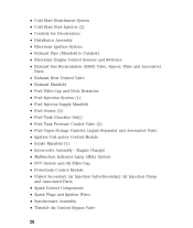
...Fuel Tank Pressure Control Valve (2) • Fuel Vapor Storage Canister, Liquid Separator and Associated Parts • Ignition Coil and/or Control Module • Intake Manifold (1) • Intercooler Assembly - Engine Charger • Malfunction Indicator Lamp (MIL) System • PCV System and ...Oil Filler Cap • Powertrain Control Module • Pulsed Secondary Air Injection Valve/Secondary Air Injection Pump and Associated Parts • Spark Control Components • Spark Plugs ...
...Fuel Tank Pressure Control Valve (2) • Fuel Vapor Storage Canister, Liquid Separator and Associated Parts • Ignition Coil and/or Control Module • Intake Manifold (1) • Intercooler Assembly - Engine Charger • Malfunction Indicator Lamp (MIL) System • PCV System and ...Oil Filler Cap • Powertrain Control Module • Pulsed Secondary Air Injection Valve/Secondary Air Injection Pump and Associated Parts • Spark Control Components • Spark Plugs ...

Audio Guide 1st Printing
Page 26
...power lines, electric fences, traffic lights and thunderstorms. Moving away from an interfering 26 This range can be caused on AM stations by "signal modulation." The further the FM signal travels, the weaker it is approximately 40 km (24 miles). Allowable frequencies are: AM 530-1610 kHz in ...kHz steps FM 87.9-107.9 MHz in 0.2 MHz steps Not all frequencies are used in a given area. Hills, mountains and tall buildings between your vehicle's antenna and the radio station signal can cause FM signal reception problems. Static can affect radio reception: • ...
...power lines, electric fences, traffic lights and thunderstorms. Moving away from an interfering 26 This range can be caused on AM stations by "signal modulation." The further the FM signal travels, the weaker it is approximately 40 km (24 miles). Allowable frequencies are: AM 530-1610 kHz in ...kHz steps FM 87.9-107.9 MHz in 0.2 MHz steps Not all frequencies are used in a given area. Hills, mountains and tall buildings between your vehicle's antenna and the radio station signal can cause FM signal reception problems. Static can affect radio reception: • ...


