Scheduled Maintenance Guide 3rd Printing
Page 9
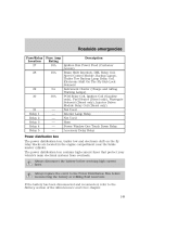
... and clean body and door drain holes safety warning lamps (brake, ABS, air bag, safety belt) for operation cooling system fluid level and coolant strength battery water level (non-maintenance free) battery connections and clean if necessary clutch fluid level, if equipped 9
... and clean body and door drain holes safety warning lamps (brake, ABS, air bag, safety belt) for operation cooling system fluid level and coolant strength battery water level (non-maintenance free) battery connections and clean if necessary clutch fluid level, if equipped 9
7.3L Diesel Supplement 1st Printing
Page 11
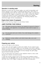
...damage. Consult your dealer for contamination. Do not attach the jumper cables to flames, sparks, or lit cigarettes. Do not disconnect the battery of the disabled vehicle as this could result in the Workshop Manual, then check the engine oil for service immediately. An explosion could... damage the vehicle's electrical system. 3. If you connect your battery to a 24-volt power supply you can explode if exposed to the glow plug relay as this could damage the catalytic converter. Engine ...
...damage. Consult your dealer for contamination. Do not attach the jumper cables to flames, sparks, or lit cigarettes. Do not disconnect the battery of the disabled vehicle as this could result in the Workshop Manual, then check the engine oil for service immediately. An explosion could... damage the vehicle's electrical system. 3. If you connect your battery to a 24-volt power supply you can explode if exposed to the glow plug relay as this could damage the catalytic converter. Engine ...
7.3L Diesel Supplement 1st Printing
Page 12
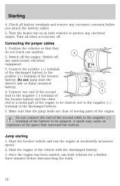
...protect any unnecessary electrical + equipment. 3. Turn the heater fan on in both vehicles for a further three minutes before you attach the battery cables. 5. Connect one another. 4 1 2. Jump starting 1. Start the booster vehicle and run both vehicles to the negative (-) terminal of the booster..., run the engine at moderately increased speed. 2. Connecting the jumper cables 1. Starting 4. Start the engine of the gases that surround the battery. Check all other end to a metal part of the engine. - Switch off the engine. Position the vehicles so that the jump leads ...
...protect any unnecessary electrical + equipment. 3. Turn the heater fan on in both vehicles for a further three minutes before you attach the battery cables. 5. Connect one another. 4 1 2. Jump starting 1. Start the booster vehicle and run both vehicles to the negative (-) terminal of the booster..., run the engine at moderately increased speed. 2. Connecting the jumper cables 1. Starting 4. Start the engine of the gases that surround the battery. Check all other end to a metal part of the engine. - Switch off the engine. Position the vehicles so that the jump leads ...
7.3L Diesel Supplement 1st Printing
Page 13
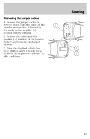
Remove the cable from the positive (+) terminal of the booster battery and then the discharged battery. 3. Starting Removing the jumper cables 1. After the disabled vehicle has been started, allow it to idle for a while so the engine can "relearn" its idle conditions. 1 4 + - - + 3 2 13 Remove the jumper cables in reverse order. Take the cable off the metallic surface first, followed by the cable on the negative (-) booster battery terminal. 2.
Remove the cable from the positive (+) terminal of the booster battery and then the discharged battery. 3. Starting Removing the jumper cables 1. After the disabled vehicle has been started, allow it to idle for a while so the engine can "relearn" its idle conditions. 1 4 + - - + 3 2 13 Remove the jumper cables in reverse order. Take the cable off the metallic surface first, followed by the cable on the negative (-) booster battery terminal. 2.

7.3L Diesel Supplement 1st Printing
Page 17
In "Charge Protection" mode, the battery voltage is monitors and the engine idle speed is increased so the battery charge is the recommended method of elevating idle speed for PTO applications. LCD screen Displays current engine speed and battery voltage. This is maintained as required. It has the following features:... RPM control This feature is used for maintaining battery charge. RPM CONTROL CHARGE PROTECT POWER Charge Protect This feature is used for elevating the engine's idle speed. RPM CONTROL CHARGE ...
In "Charge Protection" mode, the battery voltage is monitors and the engine idle speed is increased so the battery charge is the recommended method of elevating idle speed for PTO applications. LCD screen Displays current engine speed and battery voltage. This is maintained as required. It has the following features:... RPM control This feature is used for maintaining battery charge. RPM CONTROL CHARGE PROTECT POWER Charge Protect This feature is used for elevating the engine's idle speed. RPM CONTROL CHARGE ...
7.3L Diesel Supplement 1st Printing
Page 34
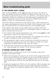
.... • Leaving the ignition key ON for the starter to operate. • Try operating the starter switch several times. Check the battery connections at the battery posts, cable connection to the engine grounding point and at the starter terminal. If the starter relay clicks, but the starter does not ...will cease activation. Minor troubleshooting guide IF THE ENGINE WON'T CRANK Turn on at all electrical connections are dim, do not go out, the battery connections may be out of 30 seconds) could cause damage to the starter motor. • Check the fuel gauge. If the lights are ...
.... • Leaving the ignition key ON for the starter to operate. • Try operating the starter switch several times. Check the battery connections at the battery posts, cable connection to the engine grounding point and at the starter terminal. If the starter relay clicks, but the starter does not ...will cease activation. Minor troubleshooting guide IF THE ENGINE WON'T CRANK Turn on at all electrical connections are dim, do not go out, the battery connections may be out of 30 seconds) could cause damage to the starter motor. • Check the fuel gauge. If the lights are ...

Owner Guide 4th Printing
Page 12
LOW RANGE 4x4 12 High beams Illuminates when the high beam headlamps are turned on . The light also illuminates when the battery is engaged. Illuminates when four-wheel drive low is not charging properly, requiring electrical system service. Four wheel drive indicator (if equipped) This light momentarily ...
LOW RANGE 4x4 12 High beams Illuminates when the high beam headlamps are turned on . The light also illuminates when the battery is engaged. Illuminates when four-wheel drive low is not charging properly, requiring electrical system service. Four wheel drive indicator (if equipped) This light momentarily ...

Owner Guide 4th Printing
Page 16
... moves and stays outside the normal operating range (as indicated), have the vehicle's electrical system checked as soon as possible. 18 8 16 Battery voltage gauge This gauge shows the battery voltage when the ignition is in the red zone may damage the engine. Driving with your tachometer pointer in the ON position...
... moves and stays outside the normal operating range (as indicated), have the vehicle's electrical system checked as soon as possible. 18 8 16 Battery voltage gauge This gauge shows the battery voltage when the ignition is in the red zone may damage the engine. Driving with your tachometer pointer in the ON position...

Owner Guide 4th Printing
Page 78
Operation is powered by one coin type three-volt lithium battery CR2032 or equivalent. Changes or modifications not expressly approved by : • weather conditions • nearby radio towers • structures around the vehicle • other ...: (1) This device may not cause harmful interference, and (2) This device must accept any interference received, including interference that may cause undesired operation. Replacing the battery The transmitter is subject to 10 meters (33 feet) away from your vehicle. Controls and features Sounding a panic alarm Press this control to ACC or...
Operation is powered by one coin type three-volt lithium battery CR2032 or equivalent. Changes or modifications not expressly approved by : • weather conditions • nearby radio towers • structures around the vehicle • other ...: (1) This device may not cause harmful interference, and (2) This device must accept any interference received, including interference that may cause undesired operation. Replacing the battery The transmitter is subject to 10 meters (33 feet) away from your vehicle. Controls and features Sounding a panic alarm Press this control to ACC or...
Owner Guide 4th Printing
Page 79
... or when the ignition is used to the OFF position. 79 The inside the transmitter unit. 3. Twist a thin coin between the two halves of new battery in the same orientation. Snap the two halves back together. The dome lamp control (if equipped) must not be set to the OFF position for... the illuminated entry system to the RUN or ACC position. Controls and features To replace the battery: 1. Place the positive (+) side of the transmitter near the key ring. The system automatically turns off if: • they have been turned on with the...
... or when the ignition is used to the OFF position. 79 The inside the transmitter unit. 3. Twist a thin coin between the two halves of new battery in the same orientation. Snap the two halves back together. The dome lamp control (if equipped) must not be set to the OFF position for... the illuminated entry system to the RUN or ACC position. Controls and features To replace the battery: 1. Place the positive (+) side of the transmitter near the key ring. The system automatically turns off if: • they have been turned on with the...
Owner Guide 4th Printing
Page 148
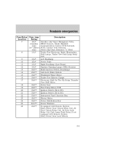
... Coil, PCM (Gasoline only) Not Used Air Bag Module, Passenger Air Bag Activation Switch, Blower Motor Relay Coil Electronic Flasher Blend Door Actuator, Trailer Tow Battery Charge Relay Coil 4-Wheel Anti-Lock Brake System (4WABS) Module Not Used 16 17 18 19 15A - - 10A 20 21 22 23 24 25 26...
... Coil, PCM (Gasoline only) Not Used Air Bag Module, Passenger Air Bag Activation Switch, Blower Motor Relay Coil Electronic Flasher Blend Door Actuator, Trailer Tow Battery Charge Relay Coil 4-Wheel Anti-Lock Brake System (4WABS) Module Not Used 16 17 18 19 15A - - 10A 20 21 22 23 24 25 26...
Owner Guide 4th Printing
Page 149
...trailer tow and electronic shift on the fly relay blocks are located in the engine compartment near the brake master cylinder. If the battery has been disconnected and reconnected, refer to the Power Distribution Box before servicing high current fuses. Not Used - Not Used - Power...The power distribution box contains high-current fuses that protect your vehicle's main electrical systems from overloads. Always replace the cover to the Battery section of the Maintenance and Care chapter. 149 Horn - Roadside emergencies Fuse/Relay Location 27 28 Fuse Amp Description Rating 10A Ignition...
...trailer tow and electronic shift on the fly relay blocks are located in the engine compartment near the brake master cylinder. If the battery has been disconnected and reconnected, refer to the Power Distribution Box before servicing high current fuses. Not Used - Not Used - Power...The power distribution box contains high-current fuses that protect your vehicle's main electrical systems from overloads. Always replace the cover to the Battery section of the Maintenance and Care chapter. 149 Horn - Roadside emergencies Fuse/Relay Location 27 28 Fuse Amp Description Rating 10A Ignition...
Owner Guide 4th Printing
Page 151
... Headlamp Power Point Right Headlamp (Low Beam) Daytime Running Lamps (DRL) Resistor Multi-function Switch, Headlamps Anti-Lock Brake System Windshield Wiper Motor Trailer Tow Battery Charge Electronic Shift On The Fly Relay, Transfer Case Shift Motor Power Seat Fuel Pump Motor, PCM Ignition Switch (B4 & B5) Ignition Switch (B1 & B3...
... Headlamp Power Point Right Headlamp (Low Beam) Daytime Running Lamps (DRL) Resistor Multi-function Switch, Headlamps Anti-Lock Brake System Windshield Wiper Motor Trailer Tow Battery Charge Electronic Shift On The Fly Relay, Transfer Case Shift Motor Power Seat Fuel Pump Motor, PCM Ignition Switch (B4 & B5) Ignition Switch (B1 & B3...
Owner Guide 4th Printing
Page 152
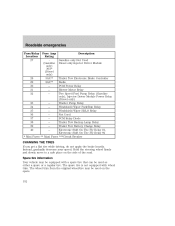
... Park/Run Relay 35 -Windshield Wiper HI/LO Relay 36 -Not Used 37 -PCM Relay Diode 38 -Trailer Tow Backup Lamp Relay 39 -Trailer Tow Battery Charge Relay 40 -Electronic Shift On The Fly Relay #1, Electronic Shift On The Fly Relay #2 * Mini Fuses ** Maxi Fuses ***Circuit Breaker CHANGING THE TIRES If...
... Park/Run Relay 35 -Windshield Wiper HI/LO Relay 36 -Not Used 37 -PCM Relay Diode 38 -Trailer Tow Backup Lamp Relay 39 -Trailer Tow Battery Charge Relay 40 -Electronic Shift On The Fly Relay #1, Electronic Shift On The Fly Relay #2 * Mini Fuses ** Maxi Fuses ***Circuit Breaker CHANGING THE TIRES If...
Owner Guide 4th Printing
Page 163
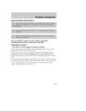
...and level. 5. Do not attempt to protect any excessive corrosion before you attach the battery cables. Turn the heater fan on both vehicles to push start your vehicle. Do not disconnect the battery of the disabled vehicle making sure the two vehicles do not have push-start your ...vehicle 1. Do not push start capability. Turn all battery terminals and remove any electrical surges. Park the booster vehicle close to flames, sparks, or lit cigarettes. An explosion could damage ...
...and level. 5. Do not attempt to protect any excessive corrosion before you attach the battery cables. Turn the heater fan on both vehicles to push start your vehicle. Do not disconnect the battery of the disabled vehicle making sure the two vehicles do not have push-start your ...vehicle 1. Do not push start capability. Turn all battery terminals and remove any electrical surges. Park the booster vehicle close to flames, sparks, or lit cigarettes. An explosion could damage ...

Owner Guide 4th Printing
Page 164
Roadside emergencies Connecting the jumper cables 1. Connect the other end of the positive (+) cable to the positive (+) terminal of the discharged battery. Note: In the illustrations, lightning bolts are used to the positive (+) terminal of the assisting battery. 164 - - - + - + + + Connect the positive (+) booster cable to designate the assisting (boosting) battery. 2.
Roadside emergencies Connecting the jumper cables 1. Connect the other end of the positive (+) cable to the positive (+) terminal of the discharged battery. Note: In the illustrations, lightning bolts are used to the positive (+) terminal of the assisting battery. 164 - - - + - + + + Connect the positive (+) booster cable to designate the assisting (boosting) battery. 2.

Owner Guide 4th Printing
Page 165
... cause an explosion of the stalled vehicle's engine, away from the battery and the carburetor/fuel injection system. Be sure that surround the battery. 5. Connect the negative (-) cable to the negative (-) terminal of the battery to the negative (-) terminal of the assisting battery. 4. Do not connect the end of the second cable to be...
... cause an explosion of the stalled vehicle's engine, away from the battery and the carburetor/fuel injection system. Be sure that surround the battery. 5. Connect the negative (-) cable to the negative (-) terminal of the battery to the negative (-) terminal of the assisting battery. 4. Do not connect the end of the second cable to be...

Owner Guide 4th Printing
Page 166
Start the engine of the booster vehicle's battery. 166 - - - - + + + + Remove the jumper cable from the ground metal surface. 2. Removing the jumper cables Remove the jumper cables in the reverse order that they were ...
Start the engine of the booster vehicle's battery. 166 - - - - + + + + Remove the jumper cable from the ground metal surface. 2. Removing the jumper cables Remove the jumper cables in the reverse order that they were ...

Owner Guide 4th Printing
Page 167
Roadside emergencies 3. Remove the jumper cable from the positive (+) terminal of the disabled vehicle's battery. After the disabled vehicle has been started and the jumper cables removed, allow it to idle for several minutes so the engine computer can relearn its idle conditions. - - - + + - + + 167 Remove the jumper cable from the positive (+) terminal of the booster vehicle's battery. 4.
Roadside emergencies 3. Remove the jumper cable from the positive (+) terminal of the disabled vehicle's battery. After the disabled vehicle has been started and the jumper cables removed, allow it to idle for several minutes so the engine computer can relearn its idle conditions. - - - + + - + + 167 Remove the jumper cable from the positive (+) terminal of the booster vehicle's battery. 4.
Owner Guide 4th Printing
Page 169
... your vehicle. • Do not work on a hot engine. • When the engine is running, keep loose clothing, jewelry or long hair away from the battery and all fuel related parts. Maintenance and care SERVICE RECOMMENDATIONS To help you service your vehicle: • We highlight do-it-yourself items in an... enclosed space, unless you are sure you disconnect the battery, the engine must "relearn" its idle conditions before your vehicle will drive properly, as explained in the...
... your vehicle. • Do not work on a hot engine. • When the engine is running, keep loose clothing, jewelry or long hair away from the battery and all fuel related parts. Maintenance and care SERVICE RECOMMENDATIONS To help you service your vehicle: • We highlight do-it-yourself items in an... enclosed space, unless you are sure you disconnect the battery, the engine must "relearn" its idle conditions before your vehicle will drive properly, as explained in the...


