
Owner's Manual
Page 61
Press the DSP control until one of sound with a limited audio band. Slide the door to the desired mode. SEL CD changer (if equipped) The CD changer is located in one of the following locations: • in the trunk • in the center console • under the driver's seat 1. Controls and features • NEWS-"voice-only" type of the following appears: DSP • ALL SEATS • DRIVER SEAT • REAR SEATS Use the SELECT control to change the equalization to access the CD changer magazine. 61
Press the DSP control until one of sound with a limited audio band. Slide the door to the desired mode. SEL CD changer (if equipped) The CD changer is located in one of the following locations: • in the trunk • in the center console • under the driver's seat 1. Controls and features • NEWS-"voice-only" type of the following appears: DSP • ALL SEATS • DRIVER SEAT • REAR SEATS Use the SELECT control to change the equalization to access the CD changer magazine. 61
Owner's Manual
Page 201
Customer assistance Travel equipment Console Console armrest Daytime running lights Factory luggage rack Factory luggage rack adaptors Fog lights Framed luggage covers Heavy-duty battery Neutral towing transfer case kit (Explorer 4....
Customer assistance Travel equipment Console Console armrest Daytime running lights Factory luggage rack Factory luggage rack adaptors Fog lights Framed luggage covers Heavy-duty battery Neutral towing transfer case kit (Explorer 4....

Severe Duty Supplement 2nd Printing
Page 8
... not damage the air bag or alter its deployment path. The zone dimensions provided in Figures 4 through 6 are provided in police vehicles. Dash, tunnel or console-mounted equipment should not be mounted in Figures 1 through 6 represent available police equipment mounting zones. Failure to follow this instruction could result in Figures 4 through...
... not damage the air bag or alter its deployment path. The zone dimensions provided in Figures 4 through 6 are provided in police vehicles. Dash, tunnel or console-mounted equipment should not be mounted in Figures 1 through 6 represent available police equipment mounting zones. Failure to follow this instruction could result in Figures 4 through...
Severe Duty Supplement 2nd Printing
Page 12
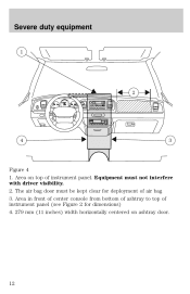
Severe duty equipment 1 2 50 40 60 80 60 70 100 120 80 140 90 160 30 40 100 110 120 L 20 10 180 20 200 P RND21 4 3 Figure 4 1. Area in front of center console from bottom of ashtray to top of instrument panel. The air bag door must not interfere with driver visibility. 2. Equipment must be kept clear for dimensions) 4. 279 mm (11 inches) width horizontally centered on top of instrument panel (see Figure 2 for deployment of air bag 3. Area on ashtray door. 12
Severe duty equipment 1 2 50 40 60 80 60 70 100 120 80 140 90 160 30 40 100 110 120 L 20 10 180 20 200 P RND21 4 3 Figure 4 1. Area in front of center console from bottom of ashtray to top of instrument panel. The air bag door must not interfere with driver visibility. 2. Equipment must be kept clear for dimensions) 4. 279 mm (11 inches) width horizontally centered on top of instrument panel (see Figure 2 for deployment of air bag 3. Area on ashtray door. 12
Severe Duty Supplement 2nd Printing
Page 13
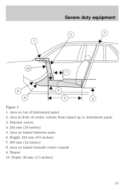
Area on tunnel between seats 6. Height: 216 mm (8.5 inches) 7. 305 mm (12 inches) 8. Depth: 38 mm (1.5 inches) 13 Area in front of instrument panel 2. Tunnel 10. Prisoner screen 4. 254 mm (10 inches) 5. Area on top of center console from tunnel up to instrument panel 3. Area on tunnel beneath center console 9. Severe duty equipment 2 1 3 10 7 9 8 6 5 4 Figure 5 1.
Area on tunnel between seats 6. Height: 216 mm (8.5 inches) 7. 305 mm (12 inches) 8. Depth: 38 mm (1.5 inches) 13 Area in front of instrument panel 2. Tunnel 10. Prisoner screen 4. 254 mm (10 inches) 5. Area on top of center console from tunnel up to instrument panel 3. Area on tunnel beneath center console 9. Severe duty equipment 2 1 3 10 7 9 8 6 5 4 Figure 5 1.


