Owner Guide 1st Printing
Page 44
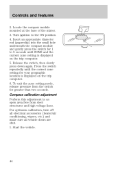
Insert an appropriate diameter rod (paperclip) into the small hole underneath the compass module and gently press the switch for your geographic location is displayed on the trip computer. 6. Start the vehicle. 44 Compass calibration adjustment Perform this adjustment... in an open area free from the switch for greater than two seconds. Locate the compass module mounted at the base of the mirror. 3. Turn ignition to 2 seconds until the correct zone setting for 1 to the ON position. 4. Press the switch repeatedly until ZONE and the ...
Insert an appropriate diameter rod (paperclip) into the small hole underneath the compass module and gently press the switch for your geographic location is displayed on the trip computer. 6. Start the vehicle. 44 Compass calibration adjustment Perform this adjustment... in an open area free from the switch for greater than two seconds. Locate the compass module mounted at the base of the mirror. 3. Turn ignition to 2 seconds until the correct zone setting for 1 to the ON position. 4. Press the switch repeatedly until ZONE and the ...
Owner Guide 1st Printing
Page 45
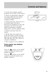
... 3. Release pressure from the switch. 6. The compass is now calibrated. Locate the compass module mounted on the trip computer. (To exit CAL mode before performing a compass adjustment, turn the ignition OFF.) 5. Insert an appropriate diameter rod (paperclip) into the switch access hole underneath the... compass module. 4. VENT VENT MODE E/M RESET 45 This will take up to five circles to...
... 3. Release pressure from the switch. 6. The compass is now calibrated. Locate the compass module mounted on the trip computer. (To exit CAL mode before performing a compass adjustment, turn the ignition OFF.) 5. Insert an appropriate diameter rod (paperclip) into the switch access hole underneath the... compass module. 4. VENT VENT MODE E/M RESET 45 This will take up to five circles to...
Owner Guide 1st Printing
Page 133
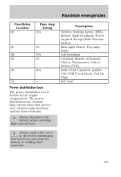
.../Relay Location 26 Fuse Amp Rating 10A Description Daytime Running Lamps (DRL) Module, Right Headlamp (Power supplied through Multi-Function Switch) Main Light Switch, Fog Lamp Relay Left Headlamp Autolamp Module, Instrument Cluster, Transmission Control Switch (TCS) Radio Noise Capacitor, Ignition Coil, PCM Power Diode, Coil On Plugs Not Used 27 28 29...
.../Relay Location 26 Fuse Amp Rating 10A Description Daytime Running Lamps (DRL) Module, Right Headlamp (Power supplied through Multi-Function Switch) Main Light Switch, Fog Lamp Relay Left Headlamp Autolamp Module, Instrument Cluster, Transmission Control Switch (TCS) Radio Noise Capacitor, Ignition Coil, PCM Power Diode, Coil On Plugs Not Used 27 28 29...
Owner Guide 1st Printing
Page 135
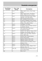
... Auxiliary A/C Relay 4 Wheel Anti-Lock Brake System (4WABS) Module Air Suspension Solid State Compressor Relay Trailer Tow Battery Charge Relay, Engine Fuse Module (Fuse 2) Shift on the Fly Relay, Transfer Case Shift relay Power Seat Control Switch Fuel Pump Relay Ignition Switch (B4 & B5) Ignition Switch (B1 & B3) Junction Box Fuse/Relay Panel Battery...
... Auxiliary A/C Relay 4 Wheel Anti-Lock Brake System (4WABS) Module Air Suspension Solid State Compressor Relay Trailer Tow Battery Charge Relay, Engine Fuse Module (Fuse 2) Shift on the Fly Relay, Transfer Case Shift relay Power Seat Control Switch Fuel Pump Relay Ignition Switch (B4 & B5) Ignition Switch (B1 & B3) Junction Box Fuse/Relay Panel Battery...


